Explanation of the process data
Standard digital output (default)
The outputs can be written directly with this standard PDO assignment, i.e. the connected actuators can be switched frame-triggered directly.
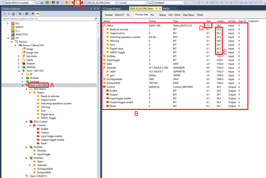 Fig.221: Standard EL2596 process image
The EL2596 (A) has input and output variables. These can be seen by expanding the tree (A). They are also displayed in the detail view (B) if the appropriate display function (C) is activated.
The bit meaning i.e. offset position can then also be taken from the memory assignment display (E), taking into account the variable size (D).
Both the collective name e.g. Status and the individual bit variable e.g. Output active can be linked, but not both at the same time.
Input data | |||
|---|---|---|---|
Collective name | Name | Description / function | Bit position [0..15] |
Status
| Ready to activate | The terminal signals its operational readiness here. This bit is 0 if there is an error. For diagnostics, see EL2596-xxxx specific diagnostics) | 0 |
Output active | The output is actively switched. | 1 | |
Switching operation counter |
| 3 | |
Warning | A warning has occurred - > evaluate “Diag data” (index 0xA000). | 6 | |
Error | An error has occurred and the output driver is deactivated - > evaluate "Diag data" (index 0xA000). | 7 | |
Digital input | The status of the digital input is returned here. | 11 | |
TxPDO Toggle | Changes its state each time process data are exchanged. | 15 | |
WcState |
| Setpoint during operation: 0 Each datagram of the EL2596 indicates its processing state here. This allows the EL2596 to be monitored for correct process data communication. |
|
InputToggle |
|
|
|
State |
| Setpoint during operation: 8 Status display of the “EtherCAT State Machine” |
|
AdsAddr |
| AMS address of the responsible EtherCAT Master in the format "0.0.0.0.0.0". In addition, the port number valid for this Slave. Required for acyclic accesses to the CoE at runtime. |
|
Output data | |||
|---|---|---|---|
Collective name | Name | Description / function | Bit position [0..15] |
Control | Enable | Activate control | 0 |
Output | Switches the output active | 1 | |
Input trigger enable | Activates the digital input as a trigger input | 3 | |
Output trigger enable | Activates the digital output as a trigger output |
| |
Reset | Resets an error | 7 | |
Standard digital output with InfoData
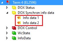 Fig.222: Additional information data
Two further cyclic data words can be displayed per channel for more exact information about the states of the actuators or the driver stage. The respective selection is to be configured via the corresponding Index 0x8002:11 or 0x8002:19 in the CoE. Among other things, the interior temperature of the terminal or the momentary current through the connected actuator can be selected, for example.
Input data | |
|---|---|
Name | Description / function |
Info data 1 | Additional channel information, definition in 0x8002:11 |
Info data 2 | Additional channel information, definition in 0x8002:19 |
External trigger input
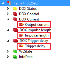 Fig.223: Additional process data in the “External trigger input” mode
In addition to the variables of the “Standard digital output” mode, there are also the following variables:
Output data | |
|---|---|
Name | Description / function |
Output current | Specification of the set current for the current control in the unit mA |
Impulse length | Specifies the length of the output pulses. The unit is 1 µs. The resolution of the time can be reduced from 1 µs to 100 ns using the CoE index 0x8002:31 Pulse resolution 100 ns. |
Trigger delay | Specifies the length of the delay from the time of the digital input to the switching of the output. The unit is 1 µs. The resolution of the time can be reduced from 1 µs to 100 ns using the CoE index 0x8002:31 Pulse resolution 100 ns. |
External trigger input with InfoData
Like both standard data types, additional information data can also be displayed in “External trigger input” mode. See above.
DC Digital output
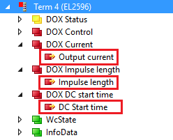 Fig.224: Additional process data for Distributed Clocks mode
In Distributed Clocks mode the EL2596 works according to timestamp order. The process image is structured correspondingly, as in the fig. Additional process data for Distributed Clocks mode.
Output data | |
|---|---|
Name | Description / function |
Output current | Specification of the set current for the current control in the unit mA |
Impulse length | Specifies the length of the output pulses. The unit is 1 µs. The resolution of the time specification can be reduced via the CoE object 0x8002:31 Pulse resolution 100 ns from 1 µs to 100 ns. |
DC Start time | 64-bit value of the next desired switching event. The data of the DC time:
|
DC Digital output with InfoData
As with the standard data, additional information data can also be shown in the “DC digital output” mode. See above.
Current control
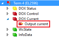 Fig.225: Additional process data in “Current control” mode
In addition to the variables of the “Standard digital output” mode, there are also the following variables:
Output data | |
|---|---|
Name | Description / function |
Output current | Specification of the set current for the current control in the unit mA |
Current control with InfoData
As with the standard data, additional information data can also be shown in the “Current control” mode. See above.
PWM
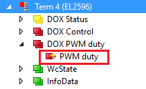 Fig.226: Additional process data in “PWM” mode
In addition to the variables of the “Standard digital output” mode, there are also the following variables:
Output data | |
|---|---|
Name | Description / function |
PWM duty | Duty cycle of the pulse width modulation |
PWM with InfoData
As with the standard data, additional information data can also be shown in the “PWM” mode. See above.
PWM with current
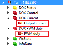 Fig.227: Additional process data in “PWM with current” mode
In addition to the variables of the “Standard digital output” mode, there are also the following variables:
Output data | |
|---|---|
Name | Description / function |
Output current | Specification of the set current for the current control in the unit mA |
PWM duty | Duty cycle of the pulse width modulation |
PWM with current and InfoData
As with the standard data, additional information data can also be shown in the “PWM with current” mode. See above.
Voltage control
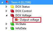 Fig.228: Additional process data in “Voltage control” mode
In addition to the variables of the “Standard digital output” mode, there are also the following variables:
Output data | |
|---|---|
Name | Description / function |
Output voltage | Specification of the set voltage for the voltage control in the unit 0.01 mV |
Voltage control with current and InfoData
As with the standard data, additional information data can also be shown in the “Voltage control” mode. See above.