LEDs and connection
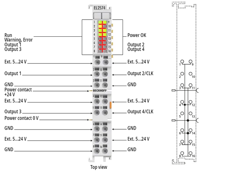 Fig.4: EL2574 connection
EL2574 - connection | ||
|---|---|---|
Terminal point | No. | Comment |
Ext. 5 … 24 V | 1 | 5 ... 24 V supply voltage for the LEDs (voltage depending on the led used; this voltage does not supply the internal electronics and is not monitored) |
Output 1 | 2 | Data output 1 |
GND | 3 | Ground of the LED supply voltage |
Ext. 5 … 24 V | 4 | 5 ... 24 V supply voltage for the LEDs (voltage depending on the led used; this voltage does not supply the internal electronics and is not monitored) |
Output 3 | 5 | Data output 3 |
GND | 6 | Ground of the LED supply voltage |
Ext. 5 … 24 V | 7 | 5 ... 24 V supply voltage for the LEDs (voltage depending on the led used; this voltage does not supply the internal electronics and is not monitored) |
GND | 8 | Ground of the LED supply voltage |
Ext. 5 … 24 V | 9 | 5 ... 24 V supply voltage for the LEDs (voltage depending on the led used; this voltage does not supply the internal electronics and is not monitored) |
Output 2 / CLK | 10 | Data output 2 / Clock output 1 |
GND | 11 | Ground of the LED supply voltage |
Ext. 5 … 24 V | 12 | 5 ... 24 V supply voltage for the LEDs (voltage depending on the led used; this voltage does not supply the internal electronics and is not monitored) |
Output 4 / CLK | 13 | Data output 4 / Clock output 2 |
GND | 14 | Ground of the LED supply voltage |
Ext. 5 … 24 V | 15 | 5 ... 24 V supply voltage for the LEDs (voltage depending on the led used; this voltage does not supply the internal electronics and is not monitored) |
GND | 16 | Ground of the LED supply voltage |
Notice | ||
 | Observe the connection instructions! Observe the information and notes in chapter"Mounting and wiring"as well as in chapter"Connection"! | |
EL2574 - LEDs
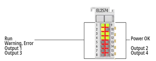 Fig.5: EL2574 LEDs
LED | Color | Meaning | |
|---|---|---|---|
RUN | green | This LED indicates the terminal's operating state: | |
off | State of the EtherCAT State Machine: INIT = initialization of the terminal | ||
flashing | State of the EtherCAT State Machine: PREOP = function for mailbox communication and different default settings set | ||
single flash | State of the EtherCAT State Machine: SAFEOP = verification of the Sync Manager channels and the distributed clocks. | ||
on | State of the EtherCAT State Machine: OP = normal operating state; mailbox and process data communication is possible | ||
flickering | State of the EtherCAT State Machine: BOOTSTRAP = function for Firmware updates of the terminal | ||
Warning, Error | yellow | Warning | |
red | Error | ||
Power OK | green | The supply to the electronics is within the permissible range. | |
Output 1 … 4 | green | The LED output is active. | |