EL2522 - LEDs and connection
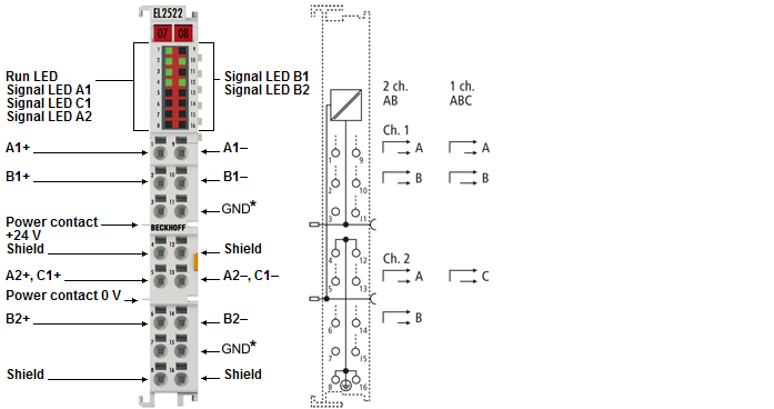
EL2522 connection
Terminal point | Description | |
|---|---|---|
Name | No. | |
Output A1+ | 1 | Output A1+ |
Output B1+ | 2 | Output B1+ |
not connected | 3 | not connected |
Shield | 4 | Shield, internally connected to pins 8, 12 and 16 |
Output A2+, C1+ | 5 | Output A2+, C1+ |
Output B2+ | 6 | Output B2+ |
not connected | 7 | not connected |
Shield | 8 | Shield, internally connected to pins 4, 12 and 16 |
Output A1- | 9 | Output A1- |
Output B1- | 10 | Output B1- |
GND | 11 | *) from hardware version 04: |
Shield | 12 | Shield, internally connected to pins 4, 8 and 16 |
Output A2-, C1- | 13 | Output A2-, C1- |
Output B2- | 14 | Output B2- |
GND | 15 | *) from hardware version 04: |
Shield | 16 | Shield, internally connected to pins 4, 8 and 12 |
LEDs EL2522
LED | Color | Meaning | |
|---|---|---|---|
Output A1, A2, B1, B2, C1 | green | The LED for the active frequency output A1, A2, B1, B2 or C1; can only be perceived as a glow at half brightness at higher frequencies. The five LEDs (A2, A2, B1, B2, C1) flash green when UP (voltage supply of the power contacts) is not available. | |
RUN | green | This LED indicates the terminal's operating state: | |
off | State of the EtherCAT State Machine: INIT = initialization of the terminal | ||
flashing | State of the EtherCAT State Machine: PREOP = function for mailbox communication and different default settings set | ||
Single flash | State of the EtherCAT State Machine: SAFEOP = verification of the Sync Manager channels | ||
on | State of the EtherCAT State Machine: OP = normal operating state; mailbox and process data communication is possible | ||
flickering/ | State of the EtherCAT State Machine: BOOTSTRAP = function for firmware updates | ||