Basic function
The EL2502-0010 has three basic operation modes with additional selection options per channel. These are accessed via the PDO selection (see figure).
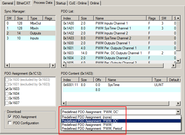
"PWM, DC": | This mode should be used if both the duty factor and the cycle duration are to be changed quickly in real-time context. In this mode a start and stop time can additionally be transferred to the terminal.
|
"PWM, period": | This mode should be used if both the duty factor and the cycle duration are to be changed quickly in real-time context.
|
"PWM": | This mode is to be used if the duty factor only is to be quickly changed in the real-time context.
|
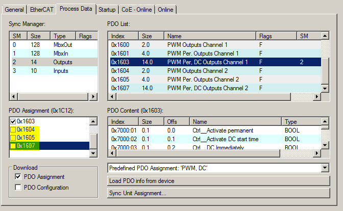
The PDOs can be assigned and the second channel can be switched on at the same time by clicking on one of the options marked yellow in the following diagram, or via PDOs 0x1A02 and 0x1A03 after selecting the inputs.
 | The temporal accuracy is impaired if the second channel is activated If a second channel is activated by selecting one of the PDO assignments 0x1604 to 0x1607 or 0x1A02, 0x1A03, please note that the additional calculations in the microcontroller slightly impair the temporal accuracy. |
Process data in PWM, DC mode
Predefined PDO Assignment 'PWM, DC' (0x1603, 0x1A00, 0x1A01) | ||||
|---|---|---|---|---|
PDO | Excluded PDOs | PDO Content | Description | Data type |
0x1A00 | None | 0x6000:01 | This is set when the temperature of the terminal exceeds 90°C. | BOOL |
0x6000:04 | This is set in the event of output overload. | BOOL | ||
0x6000:05 | This bit toggles with each correct DC event. | BOOL | ||
0x6000:06 | The new start time that was specified is in the past. | BOOL | ||
0x1A01 | None | 0x6001:11 | System time of the µController (jitter!) | ULINT |
0x1603 | 0x1600 0x1601 | 0x7000:01 | The PWM output takes place permanently with the specified data. | BOOL |
0x7000:02 | If the bit is set, a DC output with the values set via 0x7000:11 and 0x7000:12 is initiated with each new DC start time. | BOOL | ||
0x7000:03 | 1: If the bit is set, the PWM output changes immediately when the DC start time is reached, which means that output glitches may occur. 0: When the DC start time is reached, the output changes without glitches. | BOOL | ||
0x7000:04 | Resetting of the DC error counter in CoE | BOOL | ||
0x7000:05 | If there is no PWM output on the second channel (no PDO is assigned to the channel), it can be used for a DC‑synchronous output. With each new valid start time, the output of channel 2 is toggled with the DC event and the switching of the PWM unit. | BOOL | ||
0x7000:11 | The PWM output duty cycle in % 0x7FFF = 100% | UINT | ||
0x7000:12 | The default PWM period in µs | UINT | ||
0x7000:13 | The 64-bit DC start time in ns | ULINT | ||
The process data of other operating modes are described in chapter Process data.
Data flow
The parameters are considered in the following order:

Example for DC timestamp functionality
To change the PWM cycle duration and duty factor at time T1, proceed as follows:
- Set “DC start time” = TRUE
- “DC immediately” = TRUE
- “PWM output” = new duty cycle
- “PWM period” = new period
- „DC start time” = T1
Once the system time reaches time T1, the "Feedback PWM" bit toggles and the next event can be activated.
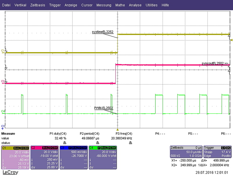
Legend for the diagrams in the following examples:
CH1 | EL2252 DC output Ch1 with the same time stamp as EL2502-0010 |
CH2 | EL2502-0010 sync. output Ch2 |
CH3 | EL2502-0010 PWM output |
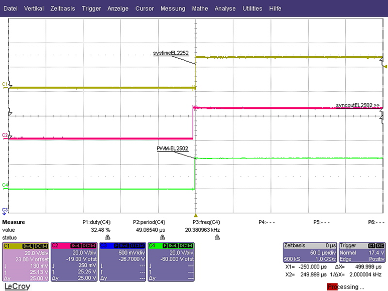
Example 1: Immediate = TRUE
- „DCSyncOutCh2” = TRUE
- „DC Immediately” = TRUE
- Activate „DC start Time” = TRUE
Example 2: Immediate = FALSE
- „DCSyncOutCh2” = TRUE
- “DC Immediately” = FALSE
- Activate „DC start Time” = TRUE
In the event of an invalid timestamp (e.g. a time in the past) the current PWM signal is switched directly to the new signal after the end of the current period, as in this example (whose parameters were transferred together with the timestamp).
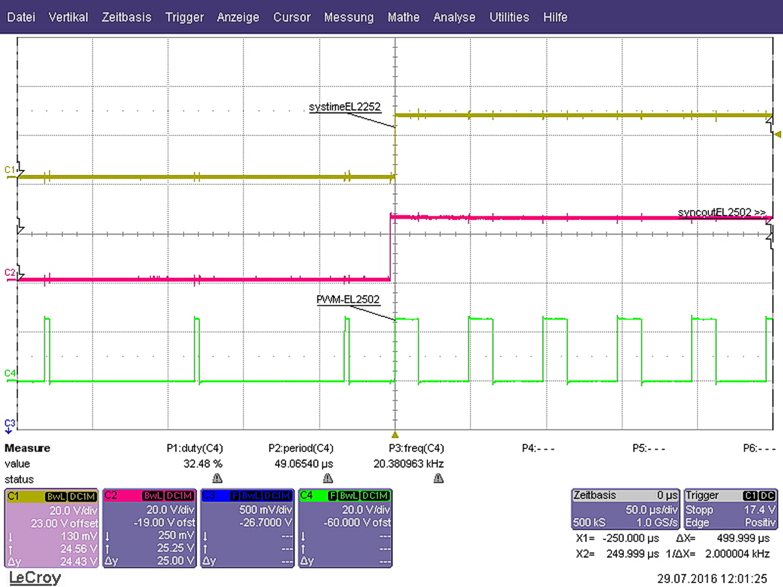
Example 3: Immediate = TRUE, duty factor 0 to 100%
- „DCSyncOutCh2” = TRUE
- „DC Immediately” = TRUE
- Activate „DC start Time” = TRUE
- PWM duty changes from 0 to 100%