Quick start
No special measures are required for commissioning the EL2212.
The EL2212 can be operated with different types of function. The course of decision making and action of the commissioning is shown below.
For comprehension, refer also to the introductory chapter on the mode of operation and the application notes.
2. Configuration
Create a configuration in the TwinCAT System Manager by manually inserting the terminal or scanning it online. Refer to installation chapter TwinCAT Development Environment regarding this.
 | EtherCAT XML Device Description If the XML description of the EL2212 is not available in your system you can download the latest XML file from the download area of the Beckhoff website (http://www.beckhoff.de/german/default.htm?download/elconfg.htm) and install it according to the installation instructions. |
3. Delivery state
The terminal behaves as follows in the delivery state or after scanning in the System Manager:
- frame-triggered SM-synchronous, no Distributed Clocks mode
- Process data Status + Control
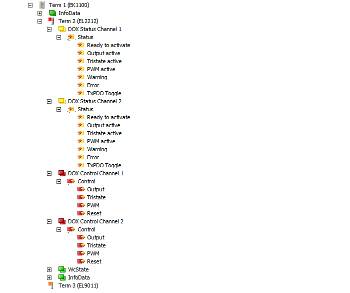 Fig.137: Default process data
Only Output needs to be used for the activation of the actuator.
- CoE settings (in this case channel 1)
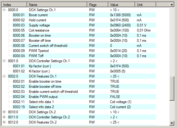 Fig.138: Default CoE-Parameter
 The fast switch-on and switch-off are activated for 1 ms each; the settings for the actuator are: 24 V supply voltage, 1 Ω internal resistance, 5 A boost and 0.5 A holding current.
These settings are to be subsequently adapted to the actuator employed.
4. Distributed Clocks mode
If you wish to use Distributed Clocks mode, change the process data and the mode of operation accordingly.
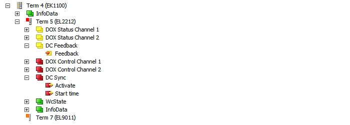 Fig.139: Process data for DC mode
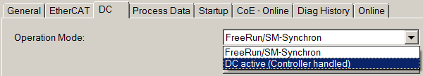 Fig.140: DistributedClocks operating mode
 Standard mode is recommended for initial functional tests of the actuator.
5. Calculation of the actuator-specific parameters
The internal resistance of the actuator must be such that the EL2212 reaches the recommended current range [0.2 – 10 A] both in the boost and the holding phase, taking into account the applied supply voltage [24 – 72 V DC].
Example: Actuator with Unom = 12 V, Ri = 8 Ω, Inom = 1.5 A.
A boost current of 4.5 A and a holding current of 0.75 A is selected. A supply voltage of at least 36 V is therefore required for the boost phase - the EL2212 does not generate this supply voltage itself! It must be generated externally and applied to the EL2212.
The durations of the boost-on and boost-off phases are each set to 25 ms. The switch-off threshold for the boost-off phase is set to -200 mA.
| Accounting for the mechanics The application notes must be taken into account in the design. |
6. Setting the parameters and process data
CoE parameters
The CoE parameters must now be stored in the CoE for each channel.
| Parameterization via the CoE list (CAN over EtherCAT) The terminal is parameterized via the CoE - Online tab (double-click on the respective object) or via the Process Data tab (allocation of PDOs). Please note the following general CoE information when using/manipulating the CoE parameters: - Keep a startup list if components have to be replaced - Differentiation between online/offline dictionary, existence of current XML description - Use "CoE reload" for resetting changes |
The over-excitation for channel 1 (n=0, activate via index 80n2:01) looks as follows in the CoE:
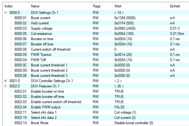 Fig.141: Specific CoE setting channel 1
for an orderly process according to
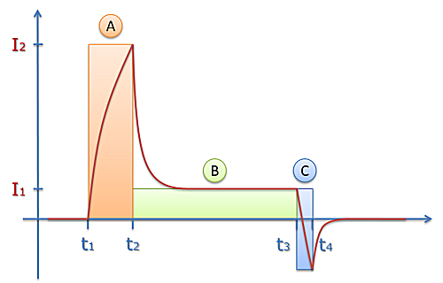 Fig.142: Current range when switching on and off
as follows:
- Phase A:
When the output is switched on (time t1), a boost current is first impressed into the actuator, the setpoint height I2 of which is determined by CoE (Index 0x80n0:01). For this purpose the necessary boost-on output voltage for the boost phase is calculated by the terminal according to U = R * I2 from 0x80n0:01 BoostCurrent and 0x80n0:05 CoilResistance. The user is recommended to perform this calculation manually beforehand and to check whether the output voltage is <= the supply voltage 0x80n0:03, because the terminal cannot output a voltage > supply voltage! How fast the current then increases in real depends on the inductance of the load. If BoosterOnTime is selected too short, the desired boost current is not reached at all.
There are 2 options here: - Voltage-controlled operation: 0x80n2:1A Boost Mode = Disabled (default).
The precalculated BoostOn output voltage is output statically/uncontrolled by the internal PWM, no current control takes place. For a well working and fast current control the supply voltage (index 0x80n0:03) and the internal resistance of the actuator (index 0x8000:05) must be specified exactly. The two values are used to calculate the feed forward control. This means that the better the feed forward is set, the less the current controller has to readjust.
Since mostly output voltage < supply voltage, the actuator is not driven as fast as it actually could. From FW11 the following current controlled operation is recommended.
Exemplary course (blue = real current, yellow = static voltage PWM).
Note: in 0x80n0:05 CoilResistance half the real resistance value is to be entered, i.e. with 5 Ω coil resistance 2.5 Ω are to be entered in the CoE. - Current-controlled operation: 0x80n2:1A Boost Mode = Enabled (from FW11).
A continuous current control takes place in the BoostOn and Boost-Off phase: in order to reach the setpoint current I2 quickly, the channel initially outputs the full supply voltage, which results in a significantly faster response of the actuator. Only later the internal PWM starts and controls to the BoostCurrent.
From FW11 on this is the recommended mode of operation (Attention: in case of exchange against EL2212 FW<11 the function is not available!)
Exemplary course (blue = real current, yellow = regulated voltage PWM)
Note: in 0x80n0:05 CoilResistance the full real resistance value is to be entered, i.e. with 5 Ω coil resistance 5 Ω are to be entered in the CoE. - Phase B:
after the time t2-t1 (index 0x80n0:06 BoosterOnTime) has elapsed, the current control changes from boost current to nominal current (index 0x80n0:02). In this range active current control takes place by the internal PWM (change of duty cycle). - Phase C:
Phase C (time t3 to t4) behaves analogous to phase A when BoosterOffTime (index 0x80n2:02) is activated, except that the EL2212 supply voltage is output inverted to the actuator. The current is measured in the process. The reverse current I(t) depends on
- the inductance
- the available supply voltage 0x80n0:05
- the above setting 0x80n2:1A Boost Mode (from FW11):
Disabled (default): see voltage controlled operation in phase A
Enabled: see current controlled operation in phase A, current control according to 0x80n0:01 Boost Current
The switch-off can be configured in two different ways. For this, the current actuator current is measured and evaluated.
- If the switch-off threshold of the actuator current is deactivated (Index 0x80n2:03 = FALSE), after the BoosterOffTime (t4-t3 , Index 0x80n0:07) has elapsed, the driver stage is switched to freewheel without further control, i.e. actuator control ends.
- If it is activated Index 0x80n2:03 = TRUE), the terminal monitors two conditions: the expiration of the BoosterOffTime and the falling below of the set current threshold CurrentSwitchOffThreshold Index 0x80n0:08). When one of the two conditions occurs, the driver stage is switched to free running here. The threshold can also assume negative values to ensure that the connected actuator is switched off safely.
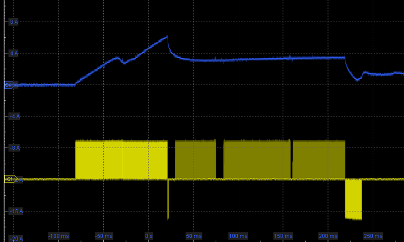 Fig.143: Voltage-controlled operation
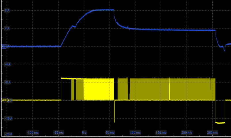 Fig.144: Current-controlled operation
The control factors (Kp, Ki, index 0x80n1:01; 0x80n1:02) should normally not be changed, because the default setting is sufficient for most applications.
For channel 2 the corresponding values in index 0x8010, 0x8011 and 0x8012 have to be changed.
Different values can be specified for each channel. The settings can also be loaded via the PLC/PLC/task at runtime.
7. Operation
If the actuator is connected, the parameterized current curve is now output with each off/on/off actuation.
The following can be used for diagnostics
- the cyclic PDO Status
- the PDO InfoData.
they can be assigned further technical information, e.g. a further, more detailed StatusWord is available there