TwinCAT 3
Startup
TwinCAT makes the development environment areas available together with Microsoft Visual Studio: after startup, the project folder explorer appears on the left in the general window area (cf. “TwinCAT System Manager” of TwinCAT 2) for communication with the electromechanical components.
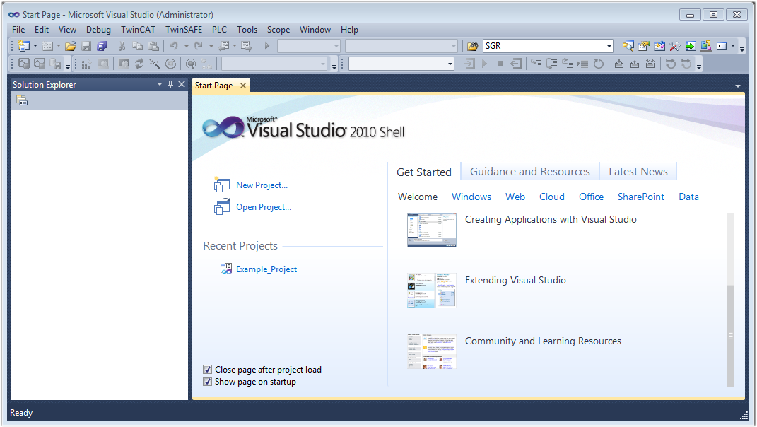
After successful installation of the TwinCAT system on the PC to be used for development, TwinCAT 3 (shell) displays the following user interface after startup:
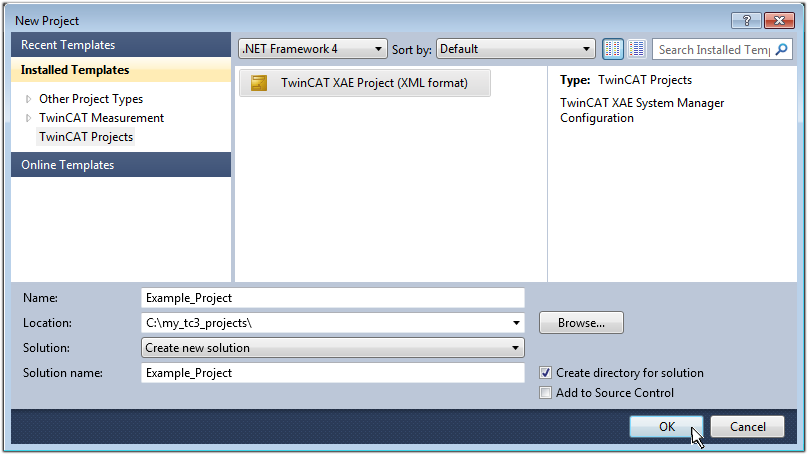
First create a new project via  (or under “File”→“New”→ “Project…”). In the following dialog make the corresponding entries as required (as shown in the diagram):
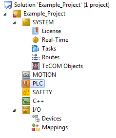
The new project is then available in the project folder explorer:
Generally, TwinCAT can be used in local or remote mode. Once the TwinCAT system including the user interface (standard) is installed on the respective PLC, TwinCAT can be used in local mode and thereby the next step is “Insert Device”.
If the intention is to address the TwinCAT runtime environment installed on a PLC as development environment remotely from another system, the target system must be made known first. Via the symbol in the menu bar:
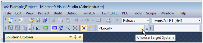
expand the pull-down menu:
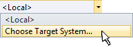
and open the following window:
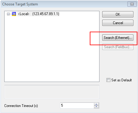
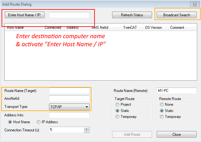
Use “Search (Ethernet)...” to enter the target system. Thus a next dialog opens to either:
- enter the known computer name after “Enter Host Name / IP:” (as shown in red)
- perform a “Broadcast Search” (if the exact computer name is not known)
- enter the known computer IP or AmsNetID.
Once the target system has been entered, it is available for selection as follows (a password may have to be entered):
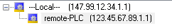
After confirmation with “OK” the target system can be accessed via the Visual Studio shell.
Adding devices
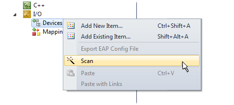
In the project folder explorer of the Visual Studio shell user interface on the left, select “Devices” within element “I/O”, then right-click to open a context menu and select “Scan” or start the action via  in the menu bar. The TwinCAT System Manager may first have to be set to “Config mode” via
  or via the menu “TwinCAT” → “Restart TwinCAT (Config mode)”.
Confirm the warning message, which follows, and select “EtherCAT” in the dialog:
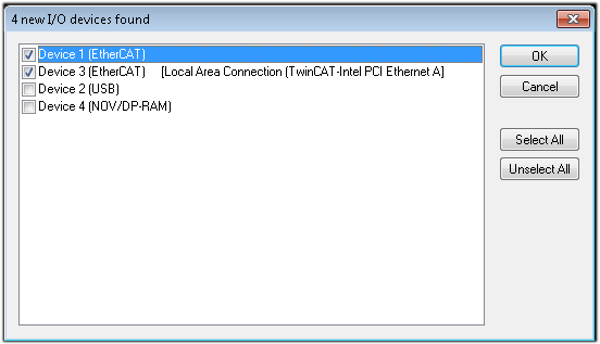
Confirm the message “Find new boxes”, in order to determine the terminals connected to the devices. “Free Run” enables manipulation of input and output values in “Config mode” and should also be acknowledged.
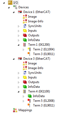
Based on the sample configuration described at the beginning of this section, the result is as follows:
The whole process consists of two stages, which may be performed separately (first determine the devices, then determine the connected elements such as boxes, terminals, etc.). A scan can also be initiated by selecting “Device ...” from the context menu, which then reads the elements present in the configuration below:
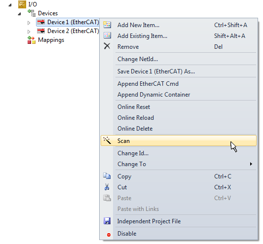
This functionality is useful if the actual configuration is modified at short notice.
Programming the PLC
TwinCAT PLC Control is the development environment for the creation of the controller in different program environments: TwinCAT PLC Control supports all languages described in IEC 61131-3. There are two text-based languages and three graphical languages.
- Text-based languages
- Instruction List (IL)
- Structured Text (ST)
- Graphical languages
- Function Block Diagram (FBD)
- Ladder Diagram (LD)
- The Continuous Function Chart Editor (CFC)
- Sequential Function Chart (SFC)
The following section refers to Structured Text (ST).
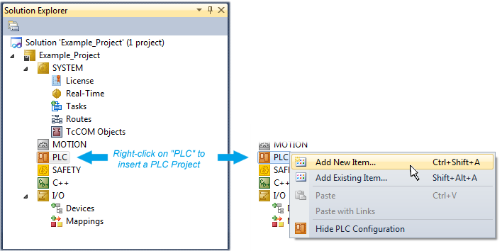
In order to create a programming environment, a PLC subproject is added to the project sample via the context menu of “PLC” in the project folder explorer by selecting “Add New Item….”:
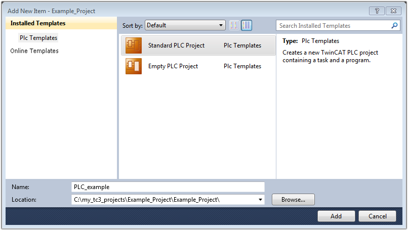
In the dialog that opens select “Standard PLC project” and enter “PLC_example” as project name, for example, and select a corresponding directory:
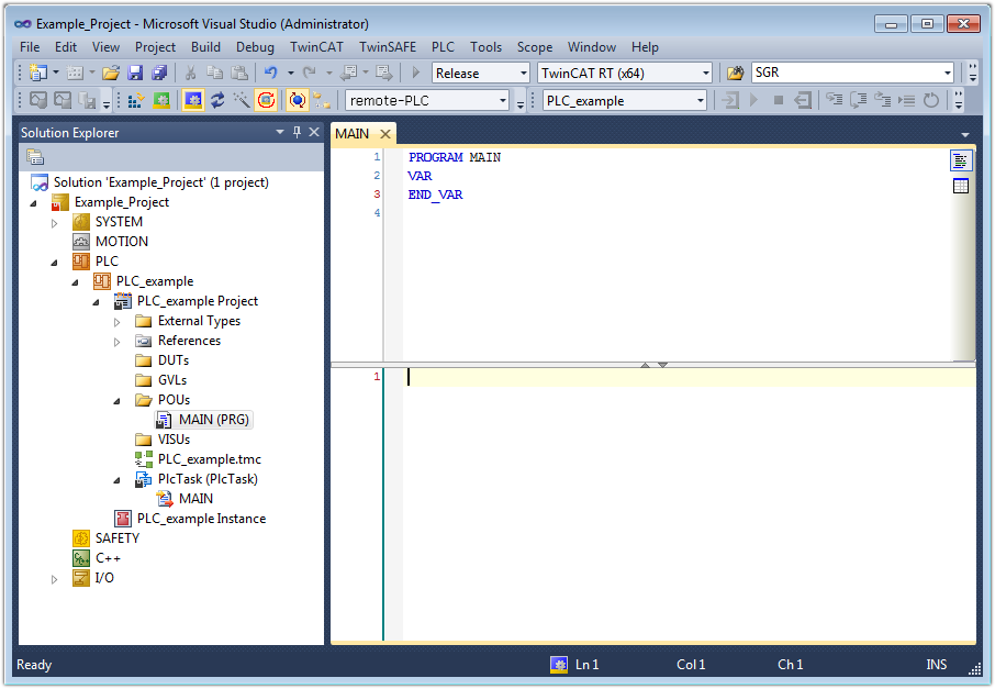
The “Main” program, which already exists by selecting “Standard PLC project”, can be opened by double-clicking on “PLC_example_project” in “POUs”. The following user interface is shown for an initial project:
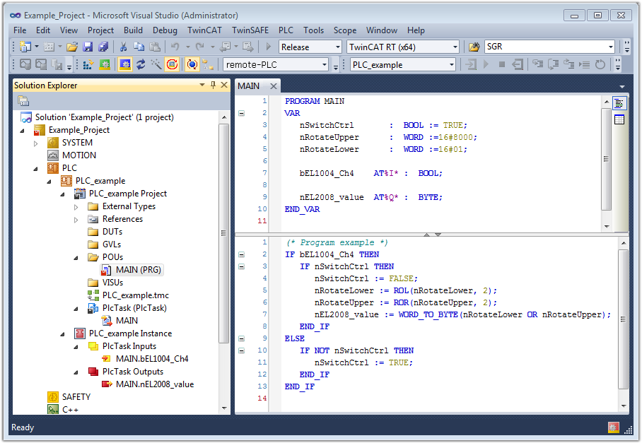
To continue, sample variables and a sample program have now been created:
The control program is now created as a project folder, followed by the compile process:
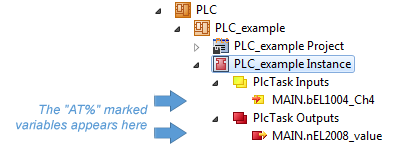
The following variables, identified in the ST/ PLC program with “AT%”, are then available in under “Assignments” in the project folder explorer:
Assigning variables
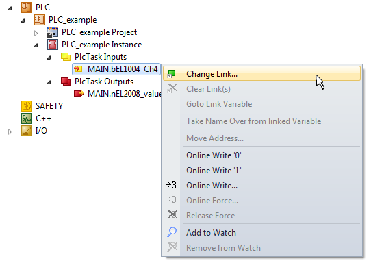
Via the menu of an instance - variables in the “PLC” context, use the “Modify Link…” option to open a window for selecting a suitable process object (PDO) for linking:
In the window that opens, the process object for the variable “bEL1004_Ch4” of type BOOL can be selected from the PLC configuration tree:
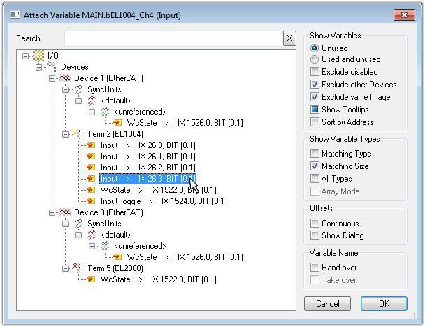
According to the default setting, certain PDO objects are now available for selection. In this sample the input of channel 4 of the EL1004 terminal is selected for linking. In contrast, the checkbox “All types” must be ticked for creating the link for the output variables, in order to allocate a set of eight separate output bits to a byte variable. The following diagram shows the whole process:
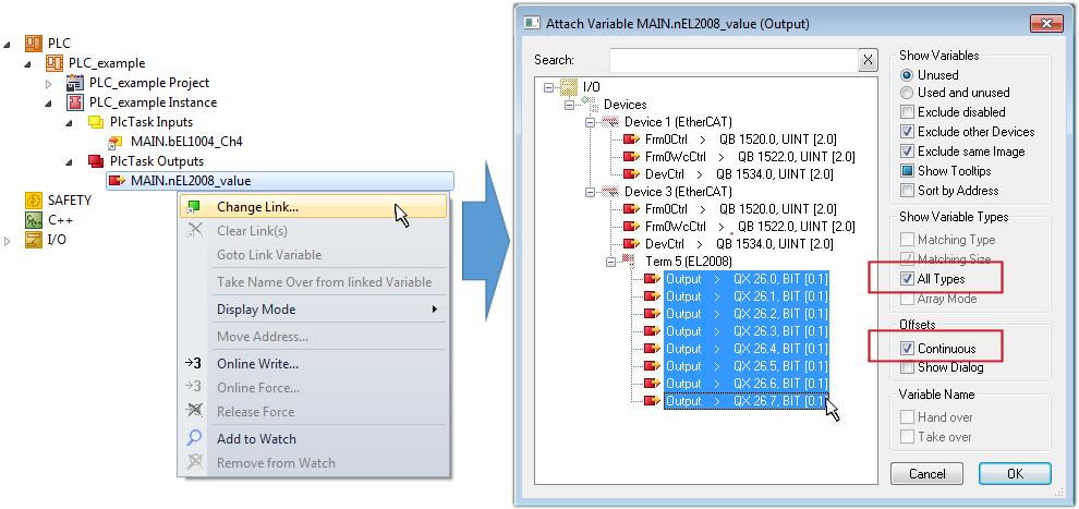
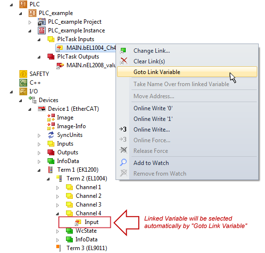
Note that the “Continuous” checkbox was also activated. This is designed to allocate the bits contained in the byte of the variable “nEL2008_value” sequentially to all eight selected output bits of the EL2008 terminal. In this way it is possible to subsequently address all eight outputs of the terminal in the program with a byte corresponding to bit 0 for channel 1 to bit 7 for channel 8 of the PLC. A special symbol ( ) at the yellow or red object of the variable indicates that a link exists. The links can also be checked by selecting a “Goto Link Variable” from the context menu of a variable. The object opposite, in this case the PDO, is automatically selected:
The process of creating links can also take place in the opposite direction, i.e. starting with individual PDOs to variable. However, in this example it would then not be possible to select all output bits for the EL2008, since the terminal only makes individual digital outputs available. If a terminal has a byte, word, integer or similar PDO, it is possible to allocate this a set of bit-standardized variables (type “BOOL”). Here, too, a “Goto Link Variable” from the context menu of a PDO can be executed in the other direction, so that the respective PLC instance can then be selected.
 | Note on the type of variable assignment The following type of variable assignment can only be used from TwinCAT version V3.1.4024.4 onwards and is only available for terminals with a microcontroller. |
In TwinCAT it is possible to create a structure from the mapped process data of a terminal. An instance of this structure can then be created in the PLC, so it is possible to access the process data directly from the PLC without having to declare own variables.
The procedure for the EL3001 1-channel analog input terminal -10...+10 V is shown as an example.
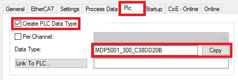
- First the required process data must be selected in the “Process data” tab in TwinCAT.
- After that, the PLC data type must be generated in the tab “PLC” via the check box.
- The data type in the “Data Type” field can then be copied using the “Copy” button.
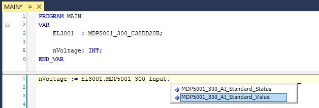
Creating a PLC data type - An instance of the data structure of the copied data type must then be created in the PLC.
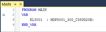
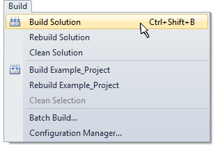
Instance_of_struct - Then the project folder must be created. This can be done either via the key combination “CTRL + Shift + B” or via the “Build” tab in TwinCAT.
- The structure in the “PLC” tab of the terminal must then be linked to the created instance.
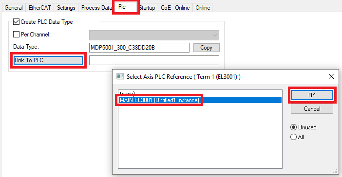
Linking the structure - In the PLC the process data can then be read or written via the structure in the program code.
Activation of the configuration
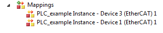
The allocation of PDO to PLC variables has now established the connection from the controller to the inputs and outputs of the terminals. The configuration can now be activated with  or via the menu under “TwinCAT” in order to transfer settings of the development environment to the runtime system. Confirm the messages “Old configurations are overwritten!” and “Restart TwinCAT system in Run mode” with “OK”. The corresponding assignments can be seen in the project folder explorer:
A few seconds later the corresponding status of the Run mode is displayed in the form of a rotating symbol  at the bottom right of the VS shell development environment. The PLC system can then be started as described below.
Starting the controller
Select the menu option “PLC” → “Login” or click on  to link the PLC with the real-time system and load the control program for execution. This results in the message No program on the controller! Should the new program be loaded?, which should be acknowledged with “Yes”. The runtime environment is ready for program start by click on symbol
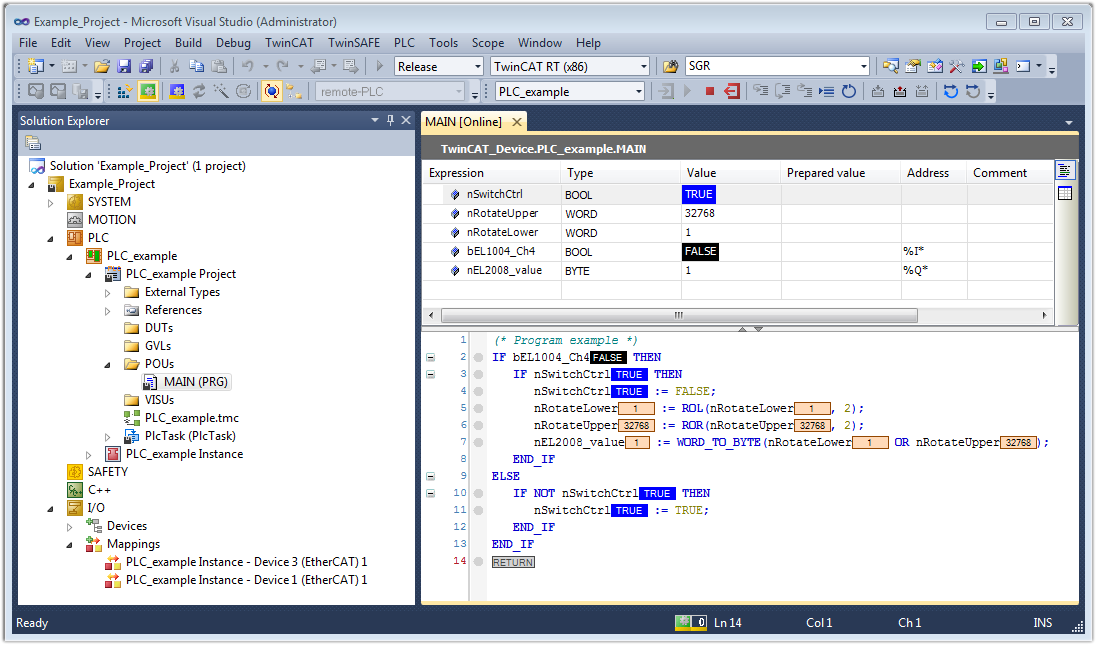
  , the “F5” key or via “PLC” in the menu selecting “Start”. The started programming environment shows the runtime values of individual variables:
The two operator control elements for stopping  and logout
  result in the required action (accordingly also for stop “Shift + F5”, or both actions can be selected via the PLC menu).