TwinCAT Quick Start
TwinCAT is a development environment for real-time control including multi-PLC system, NC axis control, programming and operation. The whole system is mapped through this environment and enables access to a programming environment (including compilation) for the controller. Individual digital or analog inputs or outputs can also be read or written directly, in order to verify their functionality, for example.
For further information please refer to http://infosys.beckhoff.com:
- EtherCAT Systemmanual:
Fieldbus Components → EtherCAT Terminals → EtherCAT System Documentation → Setup in the TwinCAT System Manager - TwinCAT 2 → TwinCAT System Manager → I/O - Configuration
- In particular, TwinCAT driver installation:
Fieldbus components → Fieldbus Cards and Switches → FC900x – PCI Cards for Ethernet → Installation
Devices contain the terminals for the actual configuration. All configuration data can be entered directly via editor functions (offline) or via the “Scan” function (online):
- “offline”: The configuration can be customized by adding and positioning individual components. These can be selected from a directory and configured.
- The procedure for offline mode can be found under http://infosys.beckhoff.com:
TwinCAT 2 → TwinCAT System Manager → IO - Configuration → Adding an I/O Device - “online”: The existing hardware configuration is read
- See also http://infosys.beckhoff.com:
Fieldbus components → Fieldbus cards and switches → FC900x – PCI Cards for Ethernet → Installation → Searching for devices
The following relationship is envisaged from user PC to the individual control elements:
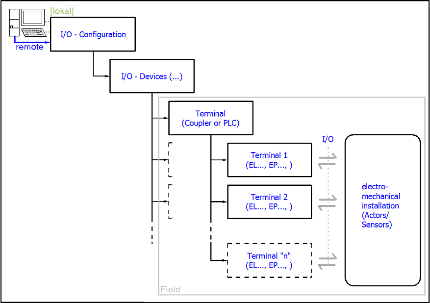
The user inserting of certain components (I/O device, terminal, box...) is the same in TwinCAT 2 and TwinCAT 3. The descriptions below relate to the online procedure.
Sample configuration (actual configuration)
Based on the following sample configuration, the subsequent subsections describe the procedure for TwinCAT 2 and TwinCAT 3:
- Control system (PLC) CX2040 including CX2100-0004 power supply unit
- Connected to the CX2040 on the right (E-bus):
EL1004 (4-channel digital input terminal 24 VDC) - Linked via the X001 port (RJ-45): EK1100 EtherCAT Coupler
- Connected to the EK1100 EtherCAT coupler on the right (E-bus):
EL2008 (8-channel digital output terminal 24 VDC; 0.5 A) - (Optional via X000: a link to an external PC for the user interface)
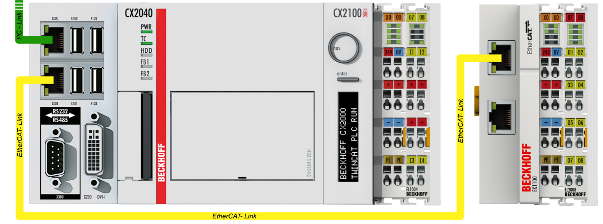
Note that all combinations of a configuration are possible; for example, the EL1004 terminal could also be connected after the coupler, or the EL2008 terminal could additionally be connected to the CX2040 on the right, in which case the EK1100 coupler wouldn’t be necessary.