Operating mode selection
The EL1512 can be operated in four operating modes: The setting takes place by the
setting of single-channel operation or operation with two separate channels through the selection of the process data objects
+
Counter settings (up/down counter, gated counter) in the CoE directory.
The following operation modes are possible:
Operation mode | Predefined PDO Assignment | Setting of the counting |
|---|---|---|
1 | 1Ch. +/- Counter: | Index 0x8020:05: 0: Enable UD counter
|
2 | Index 0x8020:05: 1: Enable pos. gate
+ Index 0x8020:04: 0: up counter | |
3 | Index 0x8020:05: 2: Enable neg. gate
+ Index 0x8020:04: 0: up counter | |
4 | 2Ch. Counter: | Index 0x8000:04 (Channel1) und 0:up counter 1:down counter |
Operating mode selection – setting of process data objects (PDO)
The process data to be transmitted (PDO, ProcessDataObjects) can be selected by the user
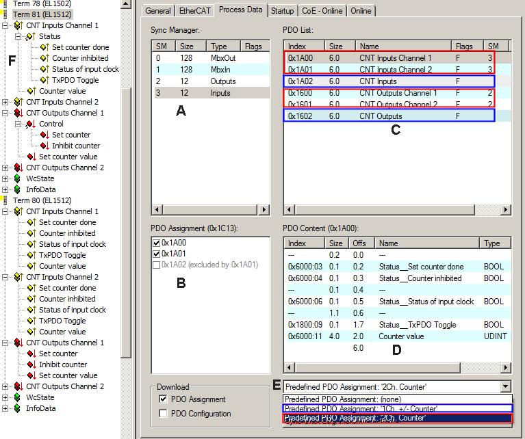
- via the "Predefined PDO Assignment" selection dialog; see fig. (E) below. The EL1512 offers a choice of two different "Predefined PDO Assignments":
- "1Ch.+/-Counter": 0x1A02 and 0x1602 (marked in blue in the figure below)
- "2Ch. Counter": 0x1A00 and 0x1600 for channel 1, 0x1A01 and 0x1601 for channel 2 (marked in red in the fig. below)
- These can be selected for individual PDOs by selecting the Sync Manager (see fig. A below) and then activating the PDOs (see fig. B below).
Exclusion criteria prevent irregular combinations. Excluded PDOs have a grey background. Therefore, for example, the PDO 0x1A02 cannot be selected as long as 0x1A00 and 0x1A01 are activated.
These changes become effective after activation and an EtherCAT restart or a reload.
The assignment of the PDOs to the respective Sync Manager is displayed in the "SM" column in the "PDO List" (see fig. C below). The contents of the PDO selected in the "PDO List" are displayed in the "PDO Content" field (see fig. D below). An overview of the assignment and contents of the PDOs can be found in the chapter "EL1512 PDO assignment".
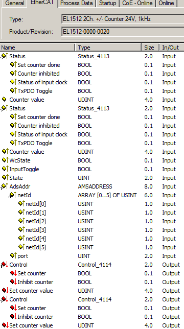
The active PDOs are displayed in the TwinCAT tree (F) and can be linked.
A detailed description of the PDO selection can be found in the chapter "detailed description of Process Data tab".
Operating mode selection – Setting in the CoE directory
Single-channel up/down counter, gated counter (operating mode 1-3)
- Selection of the predefined PDO assignment "1Ch.+/-Counter"
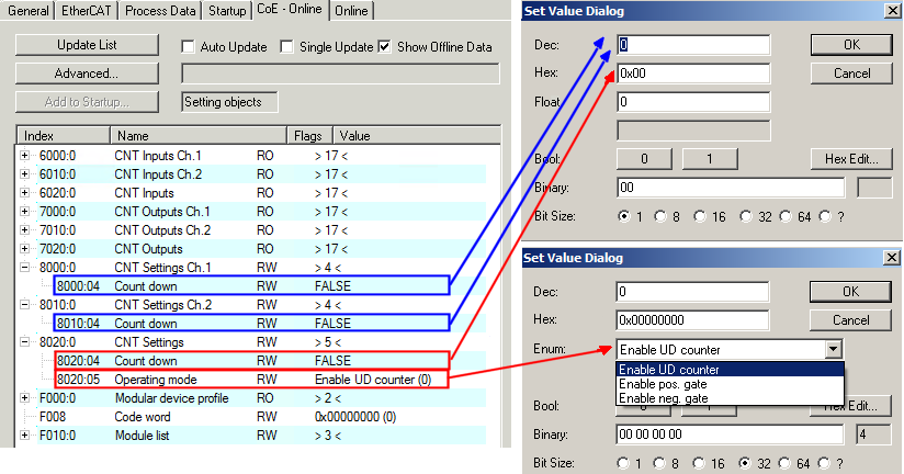
- Selection in index 0x8020:05 (see red marking in figure below). Three selection options are available in the Set Value Dialog:
- "Enable UD counter" – single-channel up/down counter (operating mode 1)
If a high signal level is encountered at the up/down input of the terminal (terminal point 1), the counter counts up in the event of positive edges at the clock input (terminal point 5), with a low signal level it counts down. - "Enable pos. gate" – single-channel gated counter locks at high level (operating mode 2)
The counter is inhibited if a high level is encountered at the gate input of the terminal (terminal point 1).
The counting direction is set by index 0x8020:04 (0: up, 1: down).
The clock input (terminal point 5) indicates the individual pulses. - "Enable neg. gate" – single-channel gated counter locks at low level (operating mode 3)
The counter is inhibited if a low level is encountered at the gate input of the terminal (terminal point 1).
The counting direction is set by index 0x8020:04 (0: up, 1: down).
The clock input (terminal point 5) indicates the individual pulses.
Two-channel up/down counter (operating mode 4)
- Selection of the predefined PDO assignment "2Ch. Counter"
The terminal points 1 or 5 serve as clock input for 32 bit counter 1 or 2. - Selection in the indices 0x8000:04 for channel 1 and 0x8010:04 for channel 2 (see blue marking in figure below). Two selection options are available per channel in the Set Value Dialog:
- 0: up counter
- 1: down counter
Please observe the notes on settings in the CoE directory