LEDs and connection
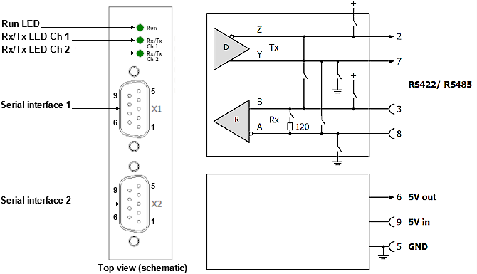 Fig.9: EL1262-0010 LEDs and connectors
EL1262-0010 LEDs
LED | Color | Meaning | |
|---|---|---|---|
RUN | green | off | State of the EtherCAT State Machine: INIT = initialization of the terminal |
flashing | State of the EtherCAT State Machine: PREOP = function for mailbox communication and different standard-settings set | ||
single flash | State of the EtherCAT State Machine: SAFEOP = check the channels of the Sync Manager and the Distributed Clocks (if supported) | ||
on | State of the EtherCAT State Machine: OP = normal operating state; mailbox and process data communication is possible | ||
flickering | State of the EtherCAT State Machine: BOOTSTRAP = function for firmware updates of the terminal | ||
LED | Color | Meaning | |
|---|---|---|---|
Signal Rx/Tx Ch(n) | Green | Off | No signal inputs activity |
On | Signal inputs activity | ||
Yellow | Off | No signal output activity | |
On | Signal outputs activity | ||
EL1262-0010 Sub-D sockets connection
Sub-D 9-pole, | Description |
|---|---|
Pin No. | |
1 | n.c |
2 | Tx+ |
3 | Rx+ |
4 | n.c. |
5 | GND |
6 | Output +5 V DC |
7 | Tx- |
8 | Rx- |
9 | Input +5 V DC |
Use of the RS interface
Level interfaces
The devices operate with a differential RS485/422 level.
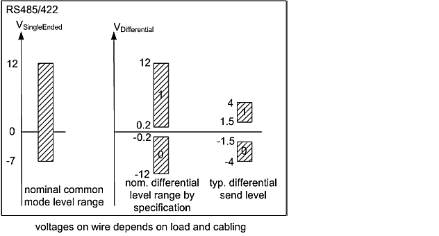 Fig.10: Level interfaces RS485/422
Termination and topology
The serial RS422 and RS485 communication technologies operate with voltage levels on a 2-wire line. Reflections at high-resistance line ends can lead to signal distortion. For this reason termination resistors are required at the receiver. For RS422/485 these are 120 Ω resistors, which together with the line resistance result in a voltage drop over the transmission link.
 | Permitted cable length The line resistance together with the termination resistor results in an overall voltage drop over the transmission link. An unacceptably high number of termination resistors would result in excessive attenuation of the signal. The system design should ensure that the voltage does not drop below 200 mV at the receiver (see Fig. ), which is the minimum voltage required. |
In RS422 mode each line must be terminated with 120 Ω at the receiver.
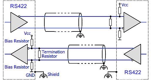 Fig.11: RS422 termination
In RS485 mode with several devices, termination resistors are only used at the two end devices.
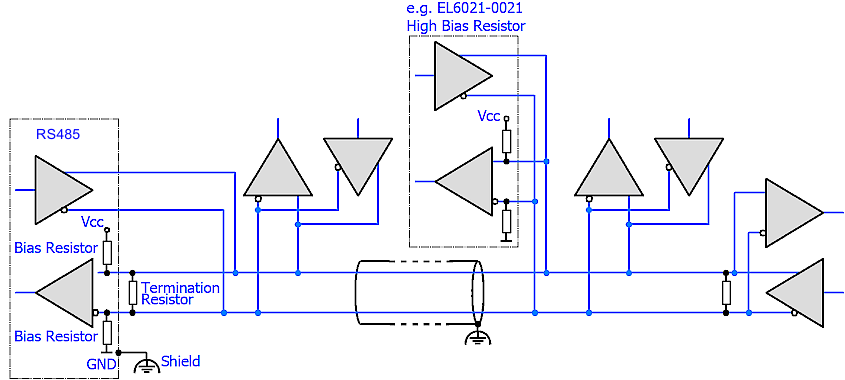 Fig.12: RS485 termination
The background is the different design of RS422/EIA-422 and RS485/EIA-485:
- RS422: 1 Rx → Tx n (maximum 10 receivers)
- RS485: n Rx → Tx m (maximum 32/128 devices, depending on the resulting bus loading)
Components for RS485 usually have a higher input impedance, resulting in lower bus load.
Topology
The termination and the bias resistors generate a load on the bus. However, they are essential for unambiguous bus levels and therefore have to be positioned with diligence. Ideally the RS422/485 bus should be configured as a daisy chain or a simple chain, see Fig. The following topologies may be problematic:
- Star topologies: each end point should ideally be terminated, but this can lead to excessive bus loading and ambiguous signal levels. Other potential issues are reflections and runtime variations.
- Intermeshed topologies: no clear end points, which means reflections and circulating currents are possible.
Shielding/shield
Notice | |
Do not use functional earth for discharge of residual currents or potential differences! The terminals offer a shielded connection for discharging EMC interference via the cable shield (FE, functional earth). The shield must not be misused for discharging residual currents or potential differences. |
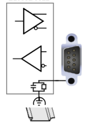 Fig.13: ShieldConnection EL1262-0010.png
The EL1262-0010 uses the RS interface "only" for electrical reasons, in order to be able to transmit the short bit times differentially. It is not an independent user for telegram-based serial communication! If the terminal is to act as a serial device, the telegram structure (7E2, 8N1...), handshake, etc. must be carried out completely on the PLC side and the corresponding bits must then be transferred to/read from the terminal via the process data.
Termination is recommended!