Commissioning an MTO channel
1. How do I test my actuator?
How do I test my actuator? Via the regular process data the outputs cannot be controlled without a time specification. The following procedure can be used to test a connected actuator without time specification:
- In the CoE directory 0x80n1:02 EnableManualOperation set the bit for the respective channel.
- If the terminal is in OP state, the PDO ManualOutputState can be set in MTO Outputs Ctrl
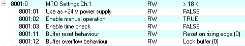 Fig.176: Manual control
The output can be set to +24 V continuous power supply. If the terminal is in OP state, the output can be activated by setting the bit in CoE 0x80n1:01 UseAs+24VPowerSupply.
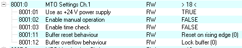 Fig.177: Output in +24 V continuous mode
2. Setting the multi-timestamping factor (MTSF)
To facilitate choosing an appropriate MTSF one should estimate how many switching orders per cycle are to be output. The multi-timestamping factor (MTSF) can then be selected. The factor indicates the maximum number of events that can be loaded into the buffer for each EtherCAT cycle.
In order to avoid the transfer of excessive quantities of process data, the following configuration recommendation applies:
MTSF ≥ expected maximum number of switching orders per EtherCAT cycle
Example: At a cycle time of 1 ms, a maximum of 5 switching orders/ms per channel are expected. All 8 channels of the EL2258 are to be used.
- MTSF = 5
- Select "Multi-Timestamping 8 Ch. 5x" via the predefined PDO.
 Fig.168: Process data selection (predefined PDO) for synchronous transfer
For each switching order an output bit in the output array (right-justified) and a timestamp are available.
These process data are placeholders for the switching orders from the PLC to the channel.
If fewer channels are required, predefined PDOs are also available for 4, 2 or 1 channel(s), with an MTSF of 1x, 2x, 5x and 10x respectively.
3. How are the outputs with timestamp activated?
Procedure during each cycle:
- Place all switching orders calculated in the PLC (output state+timestamp[32 bit]) in the PDO
- Set NoOfOutputEvents = x (e.g. x=5 if 5 valid switching orders are sent, x must be <= MTSF)
- Increment OutputOrderCounter (+ 1). This is the instruction that forces the channel to accept switching orders.
The channel returns OutputOrderFeedback = OutputOrderCounter, once it has accepted the switching orders. This is already the case in the next EtherCAT cycle, as long as the macrocycle time was not violated. Therefore two application types are possible:
- Like with a handshake, the PLC always waits to ascertain whether in the next cycle the channel has responded with OutputOrderFeedback = OutputOrderCounter before sending the next set of switching orders. This reduces the number of switching orders that can be executed per second by 50%.
- The PLC does not wait, but continuously sends new switching orders to the channel in each cycle. Nevertheless, it is advisable to check OutputOrderFeedback = OutputOrderCounter in order to ascertain whether a set of switching orders may already have been accepted in the next cycle.
If no new switching orders are to be sent to the channel during a cycle, OutputOrderCounter should simply be left unchanged.
It is recommended to always use (signed) 64-bit times in the PLC. The lower half this time variable can then simply be mapped to the channel PDO. However, note that timestamps/switching orders calculated in the PLC in this way must not be more than approx. 2 seconds in the future.