Basic principles
Each MTO channel (multi-timestamp output) has inputs and outputs in the cyclic process image, which have to be linked with the PLC/task.
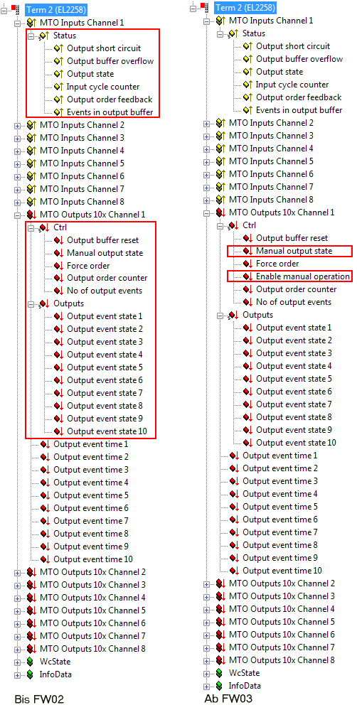 Fig.173: Inputs and outputs in the project tree
 | Additional PDO from FW03/Rev 0017 From FW03 the CtrlWord is provided with the EnableManualOperation function. This function is located at bit position 4 of the CtrlWord and is effective only if it is configured with TRUE. This bit position was previously unused. Thus also newer EL1259/EL2258 terminals can be used in the application according to the Beckhoff IO compatibility rule if a predecessor revision (e.g. 0016) is used in the configuration. Conversely, older terminals with firmware < FW03 may of course not be used in the application if this function is to be used. In general, values not equal to the default value should not be written on the application side to variables/bits that have a placeholder/reserved function and have not yet been configured with a function. The placeholders can thus be configured for future functions as in this case. |
MTO inputs returns diagnostic data in real-time for each channel:
- Status
- OutputShortCircuit: A short circuit is present at the channel.
- OutputBufferOverflow = TRUE: Indicates that more events were to be transferred at the output than can be stored in the buffer. In CoE 0x80n1:12 there is an option to select whether further new events arriving at the output are:
- no longer stored in the buffer (default), or
- stored in the buffer while older events are deleted - OutputState: State of output 0/1 for transfer to the process data via EtherCAT. This corresponds to the classic Bool output and can be used in the same way
- InputCycleCounter: The 2-bit counter is used for input process data monitoring. With each process data exchange of the terminal it is incremented by one and is reset to zero when its maximum value of three is exceeded.
- EventsInInputBuffer: Number of saved events remaining in the buffer after the events transmitted for the current cycle have been removed.
- OutputOrderFeedback: Reflects the OutputOrderCounter. Indicates whether the OutputOrderCounter was received and processed by the terminal.
MTO outputs transfers in each cycle the events to be output to the channel, together with switching state 0/1 and switching time (timestamp)
- Ctrl
- OutputBufferReset =TRUE: The channel buffer is cleared. This can make sense, e.g. in the case of a reported OutputBufferOverflow, if the application requires this.
- ManualOutputState and EnableManualOperation: This bit can be used for manual switching of the channel output.
A distinction is made between two operating modes
- In the CoE the object 0x80n1:02 EnableManualOperation can be set to TRUE. This deactivates timestamp mode for this channel. The channel can then only be switched via the bit "Manual output state".
- In the process image the bit "Enable manual operation" is set. The output assumes the state that was specified via the bit "Manual output state". In contrast to the mode described above, processing of the timestamps continues in the background. When the bit "Enable manual operation" is set to False again, the output changes to the status it was allocated through processing of the timestamps.
- ForceOrder: In the default state (i.e. FALSE) only future events are processed. Events in the past can be executed by setting this PDO (i.e. TRUE). This PDO only becomes meaningful when the object 0x80n1:03 EnableTimeCheck is activated in the CoE.
- OutputOrderCounter: New switching orders are only entered in the process image when the counter is incremented by the controller.
- NoOfOutputEvents: Number of events to be output in this process data cycle
- Output Bit Array: Bit-by-bit output states as array to the corresponding timestamps
Bit 0: Output value timestamp 1
Bit 1: Output value timestamp 2
etc.
- Output event time x: List of 32-bit timestamps of the respective signal edge.
Each channel has corresponding settings for selection of the operating mode in the CoE from 0x80n1:
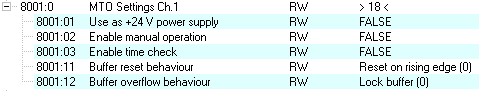 Fig.174: Operating mode selection in CoE from 0x80n1
|
0x80n1:0 MTO Settings Ch. n=0...7 |
Name |
Entry |
Description |
|---|---|---|---|
|
80n1:01 |
Use as +24 V power supply |
|
Switches the selected output in OP mode as 24 V power supply |
|
0x80n1:01 FALSE |
|
Input disabled as power supply | |
|
0x80n1:01 TRUE |
|
Input activated as power supply | |
|
80n1:02 |
Enable manual operation |
|
Manual setting of inputs (without timestamp) is enabled. This can be used to test actuators or manual procedures. |
|
0x80n1:02 FALSE |
|
Manual setting of inputs is blocked | |
|
0x80n1:02 TRUE |
|
Manual setting of inputs is possible | |
|
80n1:03 |
Enable time check |
See figure EnableTimeCheck Mode 1-3 |
Output events must be transferred chronologically. If an event with "outdated" timestamp is transferred to a channel, the following decision options are available: Mode1: Enable time check = 0, Force order = no meaning:: No "outdated" events are transferred. The system waits, including overflow (4.29s) where appropriate, after which the switching order is executed. If EnableTimeCheck is activated, the timestamp width of 4.29 seconds is subdivided into 2.15 seconds past & 2.15 seconds future. In this case switching orders may only be up to 2.15 seconds in the future. The bit ForceOrder, which is available as PDO in the status register for each channel, is used to specify how the "outdated" timestamp should be handled. |
|
0x80n1:03 FALSE | |||
|
0x80n1:03 TRUE | |||
|
80n1:11 |
Buffer reset behavior |
|
Reset behavior in the event of a reset signal in the status register (PDO) |
|
0x80n1:11 Entry FALSE |
Reset on rising edge |
Reset is executed on rising edge. New data can then be buffered right away. | |
|
0x80n1:11 Entry TRUE |
Reset on high level |
Buffer is held in reset as long as the signal is active. With high cycle times this can result in data loss. | |
|
80n1:12 |
Buffer overflow behavior |
|
Configuration of the behavior if more than 32 events per channel have to be stored |
|
0x80n1:12 Entry FALSE |
Lock buffer |
Overwriting of data is blocked, new events will be lost. | |
|
0x80n1:12 Entry TRUE |
Overwrite oldest event |
The oldest data are overwritten, new events are retained. |
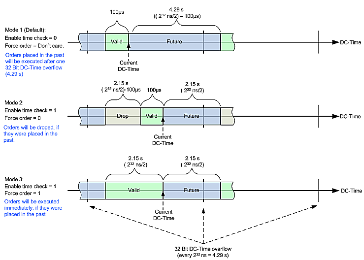 Fig.175: EnableTimeCeck Mode 1-3