Observe the following instructions in the design phase and during installation!
 | Notes on routing and installation - Differential signals (RS422) are transmitted in differential mode. In order to ensure good EMC immunity, shielded twisted-pair cables should also be used for long distances.
- The cable shield should be connected to earth potential at both channel ends and the two end devices should always be at the same reference potential.
- When using externally shielded cables, special care should be taken to avoid damaging or interrupting the shield.
- The shielding should be connected close to the plug.
- Please also observe the corresponding instructions from the sensor manufacturer!
- Observe the guidelines of the Design Guide for EtherCAT plug-in modules to ensure proper forwarding of the differential signals!
- The value of each terminating resistor should be equal to the characteristic cable impedance, typically 120 Ω for EIA-485 or RS-482 standard.
- The routing of the differential signals should be impedance-controlled with typically 120 Ω for EIA-485 or RS-482 standard. The conductor track width should be > 0.2 mm, the maximum current carrying capacity must be observed.
|
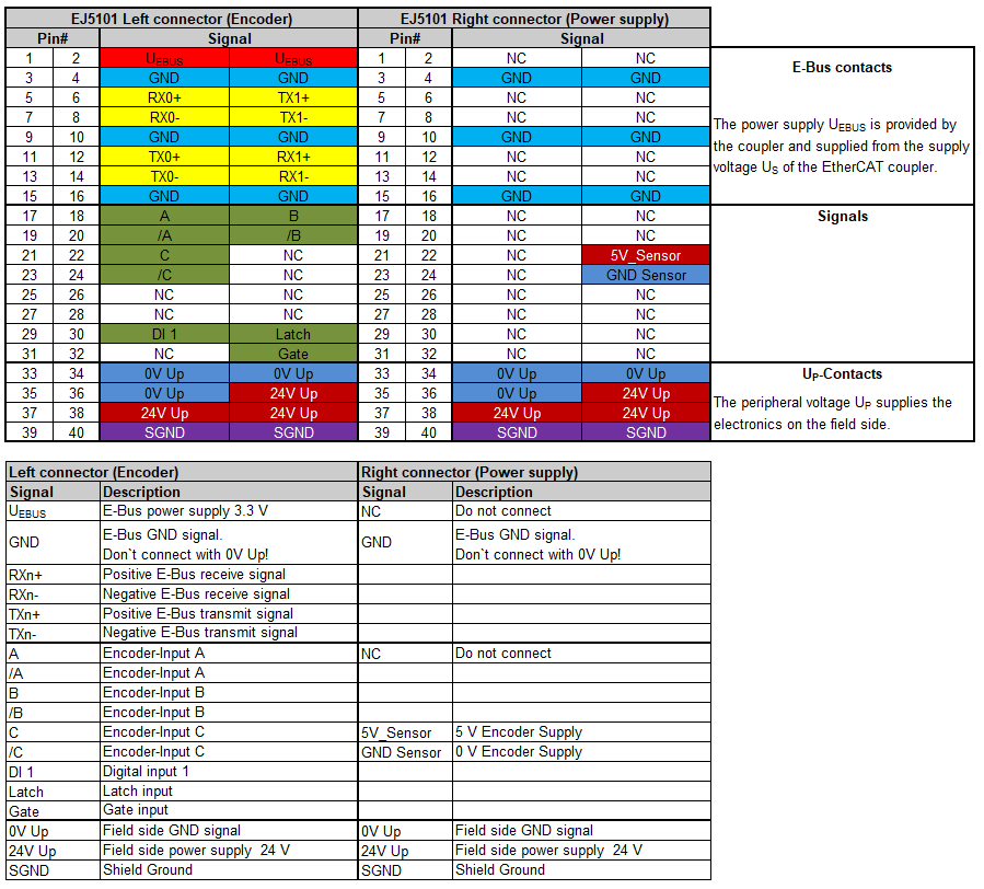 Fig.9: EJ5101 - Pinout