Connection and LEDs
| |
Risk of injury through electric shock and damage to the device! Bring the bus terminal system into a safe, de-energized state before beginning to mount, disassemble, or wire the bus terminals! |

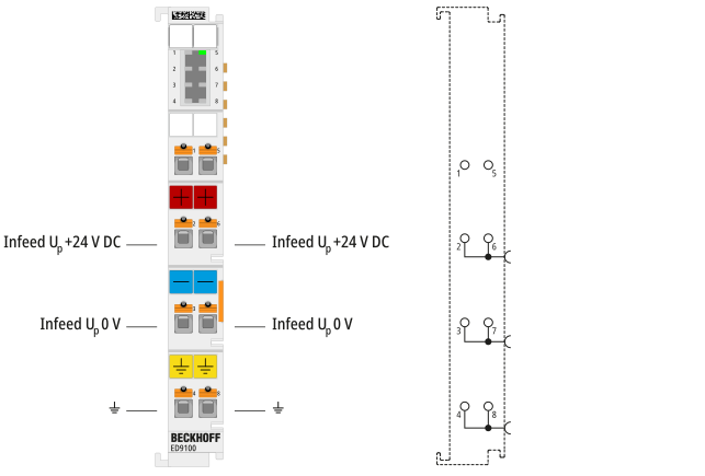
Connection
Terminal point | Description | |
|---|---|---|
Abbreviation | No. | |
n. c. | 1 | Do not connect the terminal point |
Infeed Up +24 V | 2 | Supply input +24 V (internally connected to terminal point 6 and positive power contact) |
Infeed Up 0 V | 3 | 0 V (internally connected to terminal point 7 and negative power contact) |
⏚ | 4 | Ground (internally connected to terminal point 8 and power contact ground) |
n. c. | 5 | Do not connect the terminal point |
Infeed Up +24 V | 6 | Supply input +24 V (internally connected to terminal point 2 and positive power contact) |
Infeed Up 0 V | 7 | 0 V (internally connected to terminal point 3 and negative power contact) |
⏚ | 8 | Ground (internally connected to terminal point 4 and power contact ground) |