Synchronization “Sync Settings”
The Sync0 event is specified synchronously for the entire EtherCAT network via the distributed clocks function (for details, see EtherCAT system documentation chapter “I/O synchronization via distributed clocks”). The IO-Link start and cycle time can be specified depending on the Sync0 pulse. This means that the IO-Link data can be provided synchronously across the entire EtherCAT network.
The start time for the IO-Link telegram (offset) and the IO-Link cycle can be defined in the “IO-Link” tab.
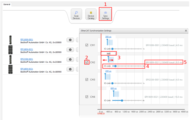 Fig.54: Settings for the IO-Link start and cycle time via “EtherCAT Synchronization Settings”
- 1. Click the “Sync Settings” button. The “EtherCAT-Synchronization Settings” dialog will open.
- 2. Activate the desired channel via the checkbox.
- 3. Specify the start time (offset) for the IO-Link telegram in relation to the Sync0 event using the slider, or enter a value in the text box.
- Equal offset times for all channels are suitable
for actuator applications such as drives, solenoid valves… - Offset times for the individual channels are suitable
, for example, for ultrasonic sensors to avoid mutual interference from superimposed signals. - 4. Use the slider to define the IO-Link cycle depending on the Sync0 cycle (see figure above (4)). Note the EtherCAT cycle time and the cycle time of the sensor (see figure above, sensor data (5)).
- 1x: New IO-Link data is provided after every Sync0 event
2x: New IO-Link data is provided after every 2nd Sync event
… - The IO-Link cycle time must not be shorter than the EtherCAT cycle time.
If an IO-Link cycle time < EtherCAT cycle time is selected, an error message is issued (see following figure). - Change the IO-Link cycle time!
- 5. The IO-Link data is provided according to the selected settings depending on the Sync0 event.
 | Note on setting the IO-Link cycle time |
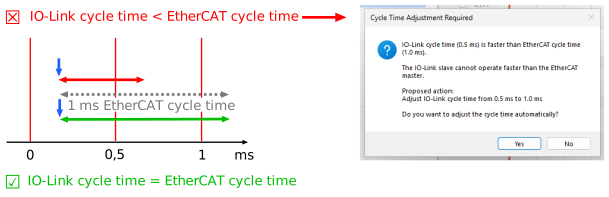 Fig.55: Error message for IO-Link cycle time < EtherCAT cycle time
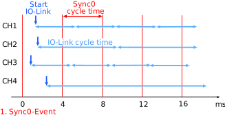 Fig.56: Schematic representation based on the settings as in the previous graphic
Sync0 event settings
The settings for the Sync0 event can be adjusted via the “DC” and “Advanced Settings” tabs.
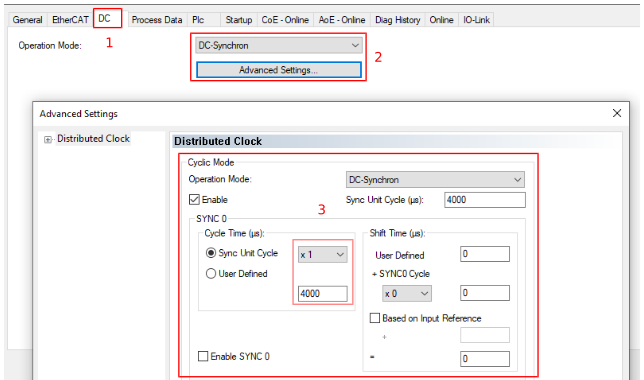 Fig.57: Specification of Sync0 cycle via the “DC” tab under “Advanced Settings”