LEDs
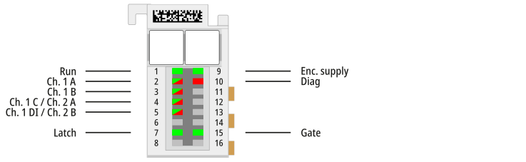
Name | No. | Color | Meaning | |
|---|---|---|---|---|
Run | 1 | green | This LED indicates the terminal’s operating state: | |
off | State of the EtherCAT State Machine: INIT = initialization of the terminal | |||
flashing | State of the EtherCAT State Machine: PREOP = function for mailbox communication and different default settings are applied | |||
single flash | State of the EtherCAT State Machine: SAFEOP = verification of the Sync Manager channels and the distributed clocks. | |||
on | State of the EtherCAT State Machine: OP = normal operating state; | |||
flickering | State of the EtherCAT State Machine: BOOTSTRAP = Function for | |||
Ch. 1 A | 2 | green, red | green: Indicates TRUE level. red: Indicates wire break at the respective input. Diagnosis is only possible if the following three conditions are met.
| |
Ch. 1 B | 3 | |||
Ch. 1 C / Ch. 2 A | 4 | |||
Ch. 2 B | 5 | |||
Ch. 1 DI | 5 | green, red | Alarm input from encoder. Input is internally connected to 5 V via a pull-up resistor. The encoder output must actively pull the signal against GND. | |
green | Output active at the encoder, a fault message is present at the encoder | |||
red | Output not active at the encoder; no fault message is present | |||
Latch | 7 | green | Lights up if a signal (+24 V) is connected to the latch input | |
Enc. supply | 9 | green | Operating voltage display for incremental encoder power supply | |
Diag | 10 | red | Initialization process active or state of the EtherCAT State Machine: BOOT | |
Gate | 15 | green | Lights up if a signal (+24 V) is connected to the gate input | |