Connection
| |
Risk of injury through electric shock and damage to the device! Bring the bus terminal system into a safe, de-energized state before beginning to mount, disassemble, or wire the bus terminals! |

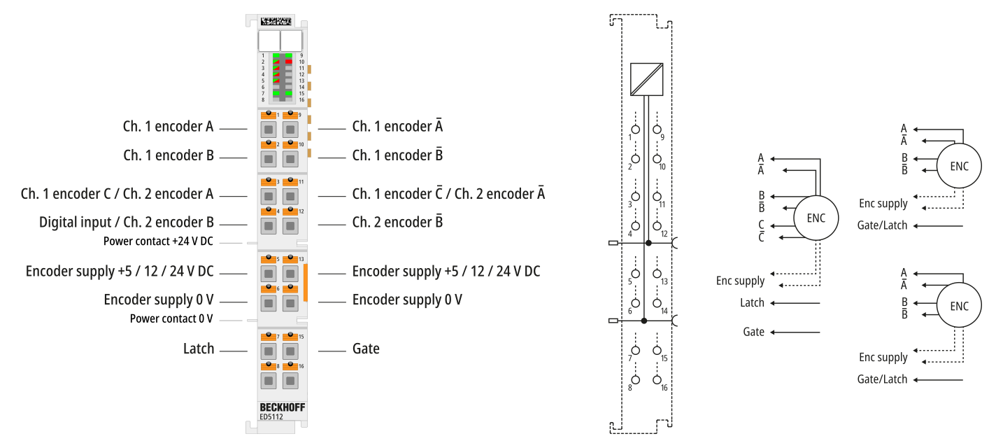
Terminal point | Description | ||
|---|---|---|---|
Abbreviation | No. | 1-channel mode 1xABC | 2-channel mode 2xAB |
Ch1 A | 1 | Channel 1, encoder input A | Channel 1, encoder input A |
Ch1 B | 2 | Channel 1, encoder input B | Channel 1, encoder input B |
Ch1 C/Ch2 A | 3 | Channel 1, encoder input C | Channel 2, encoder input A |
Ch1 DI/Ch2 B | 4 | Channel 1, digital input | Channel 2, encoder input B |
Enc supply+ | 5 | Encoder supply (5 V default, parameterizable 12 V, 24 V) | Encoder supply (5 V default, parameterizable 12 V, 24 V) |
Enc supply- | 6 | 0 V encoder supply | 0 V encoder supply |
Latch | 7 | Input “Latch extern” | Gate/Latch combination input for encoder 1 |
n.c. | 8 | Do not connect the terminal point | Do not connect the terminal point |
Ch1 A̅ | 9 | Channel 1, encoder input A̅ | Channel 1, encoder input A̅ |
Ch1 B̅ | 10 | Channel 1, encoder input B̅ | Channel 1, encoder input B̅ |
Ch1 C̅/ Ch2 A̅ | 11 | Channel 1, encoder input C̅ | Channel 2, encoder input A̅ |
Ch2 B̅ | 12 |
| Channel 2, encoder input B̅ |
Enc supply+ | 13 | Encoder supply (5 V default, parameterizable 12 V, 24 V) | Encoder supply (5 V default, parameterizable 12 V, 24 V) |
Enc supply- | 14 | 0 V encoder supply | 0 V encoder supply |
Gate | 15 | The Gate input can also be used as Latch extern 2 input | Gate/Latch combination input for encoder 2 |
n.c. | 16 | Do not connect the terminal point | Do not connect the terminal point |
 | Setting the encoder supply via index 0x8001:17 The encoder supply is set centrally for both channels via the index 0x8001:17 (channel 1). The corresponding index 0x8011:17 of the second channel has no parameterization function. |
Notice | |
Setting the encoder supply voltage
|