General information on commissioning the measuring bridge
For each channel of the measuring bridge, the measured value is calculated using the quotient of UBridge andUSense for the respective channel and specified as an mV/V value. The associated CoE indices n for the respective analog inputs per channel are listed below. This information applies to CoE objects that are described as 0x80n0.
The calculated measured values of the measuring bridge are already available as a standard configuration after a scan in TwinCAT or manually adding them to the configuration in the PDO as a Real32 value.
Channel 1 | Calculation via | PDO data type (default) | CoE-Index n |
|---|---|---|---|
RMB | UBridge Ch. 1 /USense Ch. 1 | REAL32 | 2 |
Channel 2*) | Calculation via | PDO data type (default) | CoE-Index n |
|---|---|---|---|
RMB | UBridge Ch. 2 /USense Ch. 2 | REAL32 | 6 |
*) only valid for ED3362-0x00
This means that only the default settings can be used for quick commissioning.
- Choice of the Predefined PDO "RMB Standard (Real32)" (default)
- Specifying the supply voltage (default: 10 V)
- Setting the measuring range for UBridge (default: ±20 mV)
- Setting the measuring range forUSense (default: ±12 V)
- Performing a sensor calibration
- Reading the measured value as a real value in mV/V
The optimum signal quality is achieved when using twisted-pair and shielded cables. A twisted pair should be used to connect the strain gauge power supply UExc, the sense lines USense and the bridge differential voltage UBridge.
Notice | |
Short-circuiting unused inputs Unused inputs on the same device should be properly short-circuited directly at the terminal points using short lines to prevent crosstalk! |
Bridge supply UExc
The product is designed for 4-wire or 6-wire connection. The measuring bridge can be powered by the internally generated supply voltage UExc or externally. By feeding the bridge supply voltage UExc back to the measuring point USense, the influence of line losses, temperature and drift effects is minimized.
The sensor power supply UExc is generated in the terminal from the 24 V of the power contacts and can be switched between 5 V, 10 V and OFF [external supply required].
The sensor power supply output at the UExc terminal points is not used internally. If a sensor is used that has no additional connections for supply voltage feedback in addition to connections for the UExc supply and connections for the UBridge bridge voltage, wire jumpers must be placed between the UExc and USense terminals in order to measure the supply voltage directly at the terminal.
Alternatively, the measuring bridge can be supplied by an external source. This means that the terminal can be operated in a 4-wire connection, as only the bridge voltage UBridge and the feedback of the external supply voltage USense are connected to the terminal and measured. If the bridge is supplied externally, the maximum permissible supply voltage is 12 V, as this is the full scale value for measuring the reference voltage USense.
Parallel connection of strain gauges
Parallel use of load cells is permitted. Several sensors can be connected in parallel per channel, but the maximum output power of the supply must be taken into account, as the total bridge resistance of all the strain gauges connected together is significantly reduced by the parallel connection.
Each terminal can supply a current of up to 100 mA. This means that, for example, 7 load cells with a basic resistance of 350 Ω can be connected in parallel per channel with a 5 V supply, and 3 load cells with a 10 V supply.
This specific calculation applies to internal supply and must be adjusted accordingly for external supply.
Load cells approved and calibrated by the load cell manufacturer for parallel use should be used. The nominal characteristic values [mV/V], zero offset [mV/V] and impedance [Ω, ohm] are then usually adjusted accordingly.
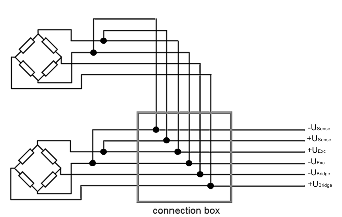 Fig.47: Parallel connection of strain gauges