Connection and LEDs
| |
Risk of injury through electric shock and damage to the device! Bring the bus terminal system into a safe, de-energized state before beginning to mount, disassemble, or wire the bus terminals! |

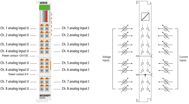
Connection
Terminal point | Description | Internally connected with connection | Max. current carrying capacity *) | |
|---|---|---|---|---|
Abbreviation | No. | |||
Ch1U | 1 | Channel 1, voltage measurement, positive input | – | Not applicable (voltage inputs) |
Ch2U | 2 | Channel 2, voltage measurement, positive input | – | |
Ch3U | 3 | Channel 3, voltage measurement, positive input | – | |
Ch4U | 4 | Channel 4, voltage measurement, positive input | – | |
Ch5U | 5 | Channel 5, voltage measurement, positive input | – | |
Ch6U | 6 | Channel 6, voltage measurement, positive input | – | |
Ch7U | 7 | Channel 7, voltage measurement, positive input | – | |
Ch8U | 8 | Channel 8, voltage measurement, positive input | – | |
Ch1I | 9 | Channel 1, current measurement, input | – | 50 mA (see note “Overcurrent protection of the 20 mA inputs”) |
Ch2I | 10 | Channel 2, current measurement, input | – | |
Ch3I | 11 | Channel 3, current measurement, input | – | |
Ch4I | 12 | Channel 4, current measurement, input | – | |
Ch5I | 13 | Channel 5, current measurement, input | – | |
Ch6I | 14 | Channel 6, current measurement, input | – | |
Ch7I | 15 | Channel 7, current measurement, input | – | |
Ch8I | 16 | Channel 8, current measurement, input | – | |
Notice | |
Cable lengths > 30 m For cable lengths > 30 m, suitable overvoltage protection (surge protection) must be provided (e g. EL9540-0010) if corresponding interference could affect the signal cable. |
 | Overcurrent protection of the 20 mA inputs The current inputs are protected against damage due to overcurrent by an internal electronic overcurrent detection with self-resetting current path separation. The overcurrent is caused by an occasionally excessive sensor voltage. Depending on the duration and level of the voltage applied, currents > 200 mA can also occur briefly (tripping time: µs range) until the current path separation becomes effective. Approximately 1 second after an overcurrent detection and the resulting current path separation, the current path is closed again. If the excessive sensor voltage is still present, an overcurrent is detected again and the current path is opened. This process is repeated as long as the excessive voltage is present (auto-retry).
|
LEDs
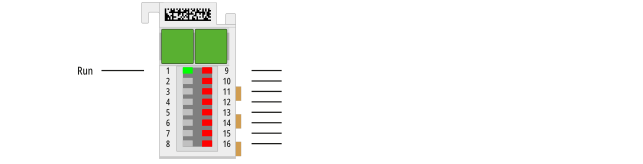
Name | No. | Color | Meaning | |
|---|---|---|---|---|
Run | 1 | green | This LED indicates the terminal’s operating state: | |
off | State of the EtherCAT State Machine: INIT = initialization of the terminal | |||
flashing | State of the EtherCAT State Machine: PREOP = function for mailbox communication and different default settings are applied | |||
single flash | State of the EtherCAT State Machine: SAFEOP = verification of the Sync Manager channels and the distributed clocks. | |||
on | State of the EtherCAT State Machine: OP = normal operating state; | |||
flickering | State of the EtherCAT State Machine: BOOTSTRAP = Function for | |||
Error Ch. 1 | 9, | red | off | No error |
On | Error is present, corresponds to PDO “Error” | |||