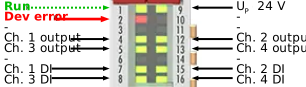
Watchdog behavior in case of a bus error
The setting in index 0x80n0:05 “Watchdog” defines how the output should assume a safe state in the event of a bus error. The following table shows the available settings.
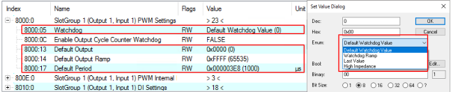 Fig.23: PWM watchdog settings in case of a bus error
Desired state | Specification in 0x80n0:05 “Watchdog” |
|---|---|
set to specified value | 0: “Default Watchdog Value” (default setting)
0x80n0:13 “Default Output”: 0x80n0:17 “Default Period”: |
set to specified value via ramp | 1: “Watchdog ramp” Using the ramp defined in index 0x80n0:14 “Default Output Ramp” (linear change [digit/ms])
|
Retain current value | 2: Last value |
Switch to high-resistance | 3: “High impedance” |
Notice | |
Apply watchdog settings for power supply units that can be configured via EtherCAT
|
Ramp
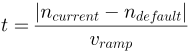
You can define the time to reach the default value when the watchdog behavior is set to the value 1 "Watchdog ramp".
|
| t: time in ms until the default value is reached. ncurrent : the last output value that was received by the controller before the communication interruption. ndefault : default value (CoE parameter 0x80n0:13). vramp : ramp velocity in digits/ms (CoE parameter 0x80n0:14). |
Tristate
In the event of a bus error, the output can be switched to a tristate state, actively to 24 V and high-impedance. The high-resistance tristate state ensures that the respective output behaves as if it were not connected. This means that the outputs of other outputs/devices connected to this output are not affected. The associated output takes on the same output voltage as the other active devices.
Diagnostics in case of bus error
The triggering of the watchdog event is indicated by:
LED 1: “Run”, LED 2: “Dev error” | Process data | DiagMessages “ |
|---|---|---|
“Run” blinks, “Dev error” lights up red
| – | Text ID: 0x8114 Output Cycle Counter watchdog has triggered Text ID: 0x8105 PD watchdog has triggered |