“HWE input (hardware enable)” | ModuleIdent 0x3009C8
This module allows you to enable or disable the PWM output via the digital input.
The status of the binary signal is output via the “HWE Inputs - Input” process data value. The HWE input module provides the following features:
- Definition of the enable level for the digital input (0x80n0:04 “Invert Digital Input”)
- Parameterizable input characteristics (0x80n0:11 “Input Type”)
- Parameterizable filter time (0x80n0:12 “Filter Time”)
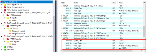 Fig.32: Settings: Digital input with enable control for the PWM output (hardware enable)
Definition of the PWM output enable level
The PWM output of the respective channel can be enabled via the digital input “Hardware Enable”. Enable is triggered by a rising edge or a falling edge.
- By default, PWM output is enabled as long as the “Inputs” process data value is set to TRUE.
- The enable level can be inverted using the settings objects (0x80n0:04 “Invert Digital Input”)
0x80n0:04 “Invert Digital Input” | Status at the digital input, “HWE inputs – input” | Output of the PWM output signal |
|---|---|---|
FALSE (default) | 1 – TRUE | is enabled |
2 – FALSE | is disabled | |
TRUE | 3 – TRUE | is disabled |
4 – FALSE | is enabled |
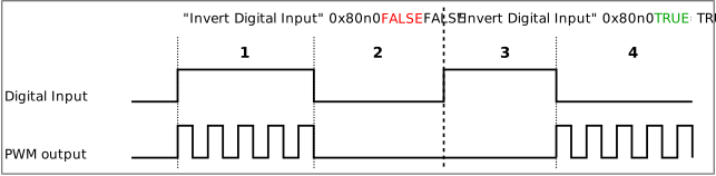 Fig.33: Enabling the PWM output signal via 0x80n0:04 “Invert digital input”
Notice | |
“Hardware enable” input in case of bus error (watchdog) The “Hardware Enable” input does not lose its functionality in the event of a bus error (watchdog). If the PWM output has been validly enabled prior to the bus error, this enable status remains in effect even during the bus error. |
Parameterizable input characteristics
The digital input can be interpreted as having either a positive switching or ground switching characteristic. This is defined at 0x80n0:11 “Input Type” (n = 1 for DI 1, n = 3 for DI 2, n = 5 for DI 3, n = 7 for DI 4):
Standard digital | Positive switching | |
|---|---|
0x80n0:11 „Input Type“ | Positive Switching (PNP) |
Signal voltage “0” | -3…+1.5 V DC |
Signal voltage “1” | 2.7…28 V DC |
Standard digital | Ground switching | |
|---|---|
0x80n0:11 „Input Type“ | Ground Switching (NPN) |
Signal voltage “0” | 2.5…28 V DC |
Signal voltage “1” | -3…+1 V DC |
In this operation mode, an additional pull-up resistor is connected to V+. | |
 | Sensors with open collector output circuits A sensor with an open collector output circuit corresponds to the “Input Type”: “Ground Switching (NPN)”.
|
Parameterizable filter time
The digital input module provides a parameterizable filter time. This can be used to suppress interference, such as bouncing of a switch signal. Signals with a pulse duration shorter than the set filter time are suppressed.
Filter function sequence
- The filter is enabled on delivery, index 0x80n0:02 “Enable Filter” = TRUE
- The filter is parameterized via index 0x8n0:12 “Filter Time”. The minimum pulse duration depends on the set software filter (see following table).
Available filter times:
Index 0x80n0:12 “Filter Time” | Meaning |
|---|---|
500dec: 500 µs | Signals < 500 µs are suppressed |
750dec: 750 µs | Signals < 750 µs are suppressed |
1,000dec: 1 ms | Signals < 1 ms are suppressed |
3,000dec: 3 ms | Signals < 3 ms are suppressed (default) |
10,000dec: 10 ms | Signals < 10 ms are suppressed |
20,000dec: 20 ms | Signals < 20 ms are suppressed |
- The filter is disabled by setting index 0x80n0:02 “Enable Filter” = FALSE. In this case, the input signal is only filtered via the hardware. In this case, the filter value is typically 10 µs.