Representing text on the display
The display can be controlled in two ways with the aid of TwinCAT. One version is programming through the System Manager. A second possibility is for the display to be written by a function block directly from the PLC program.
Settings in the System Manager
When the TwinCAT system starts, the text specified in the configuration can be written to the display. This text is set in the System Manager.
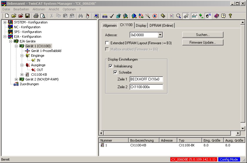
This is done by selecting the CX10x0 device in the hierarchy browser. Under the CX1100 tab it is possible to write both lines of the display in the "Display settings" area. This requires the fields at the location for initialisation and writing to be selected. The changes only take effect after the configuration has been written. When TwinCAT restarts, the set text is then displayed.

The display can be controlled directly through the Display tab. The corresponding functions are carried out immediately through the switches. It is possible to execute the following functions:
- Switch the display on/off (text is displayed/hidden)
- Background illumination on/off
- Clear the display (text is cleared, and must be re-entered)
- Cursor on/off (the cursor is displayed)
- Cursor flash on/off (the cursor flashes)
The desired text is entered into the text input field. The "Write current" switch inserts the text at the current position of the cursor.
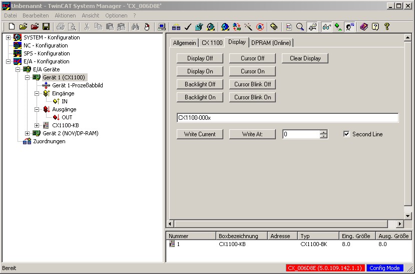
Using the "Write At" switch, the numerical input box and the "Second Line" check box, it is possible to write to a specified position on the display. The useful range of values for the position extends from 0 to 15. The user should also, however, consider the length of the text. (Each line has 16 characters!) In the example illustrated below, the text "CX1100-000x" is written to Position 0 (the start of the line) on Line 2.
Settings in the PLC program
The function block FB_CX1000SetTextDisplay is provided in the library for the CX family (TcCX1000System.lib) in order to operate the display from a PLC program. All the functions of the display can be manipulated from this function block. The library must, however, be integrated through the library administrator. If this has been done, the block is available as a function block. It is instanced as such in the declarations part of the program.
PROGRAM MAIN
VAR
    Display_0 :  FB_CX1000SetTextDisplay;
END_VAR
It is then called from the program with its parameters. There are five parameters for this function block:
- bExecute : BOOL
- nDevID : UDINT
- nMode : E_CX1000_DisplayModes
- stLine : STRING(20)
- nCursorPos : DWORD
The command is executed in response to a rising edge at "bExecute". "nDevID" provides the Device ID of the CX1100 that is to be written to. The ID is displayed in the System Manager. (The General tab for the CX1100, top right). The parameter "stLine" is used to pass a text of at most 20 characters. Only the first 16 of these characters, however, will be displayed. The writing position of the text uses quoted through "nCursorPos". 0 to 15 is a useful range for this value. "nMode" selects the operating mode of the function block. The modes are:
- e_CX1000_DisplayNoAction : No action.
- e_CX1000_DisplayOn : Switch on the display.
- e_CX1000_DisplayOff : Switch off the display.
- e_CX1000_CursorOn : Switch on the cursor.
- e_CX1000_CursorOff : Switch off the cursor.
- e_CX1000_CursorBlinkOn : Switch on the cursor flashing.
- e_CX1000_CursorBlinkOff : Switch off the cursor flashing.
- e_CX1000_BackLightOn : Switch on the background illumination.
- e_CX1000_BackLightOff : Switch off the background illumination.
- e_CX1000_ClearDisplay : Clear the content of the screen.
- e_CX1000_WriteLine1 : Write to the first line.
- e_CX1000_WriteLine1 : Write to the second line.
The call then looks like this:
Display_0(
    bExecute := write_now,      (* write_now is a boolean value, and functions as switch)
    nDevID  := 1,           (* DeviceID of the CX1100 *)
    nMode   := e_CX1000_WRITELine1, (* Write to the first line of the display *)
    stLine  := 'Beckhoff CX1100',   (* Fixed text, although variable can also be put here *)
    nCursorPos := 0         (* Writing position is 0, i.e. the start of the line *)
);
The block supplies a few status signals for evaluating the program environment. These can be used to provide feedback to the PLC program. There are three response signals from the function:
- bBusy : BOOL
- bErr : BOOL
- nErrorID : UDINT
"bBusy" indicates that the command is at present being transferred by ADS. No new command will be accepted as long as "bBusy" remains TRUE. "bErr" reports an error in a call to a function block. (The signal becomes TRUE). "nErrorID" permits the error that has occurred to be analysed by means of an error number. The error number refers to an error in the ADS protocol.