Basic function principles
The CU112x are infrastructure devices without controllable input/output data (I/O). It can be used
- as a junction point for conducted Fast Ethernet, in order to connect EtherCAT terminal stations, drives or any other EtherCAT slaves to drop lines.
- as distributed clock reference clock (see notes).
They have no I/O and no CoE directory and are not parameterizable. The core functions of the link control and distributed clocks synchronization are mapped by the ESCs.
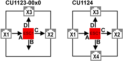
CU1123-00x0, CU1124 - Structure
The CU1123-00x0 supports three RJ45-Ports and the CU1124 supports four RJ45-Ports. For this purpose an internal communication-IC (ESC) is used. The following figure shows the structure of the internal ESC-Ports (A, B, C, D) and the designation of the connection sockets (CU1123-00x0: X1 … X3, CU1124: X1 … X4).
Please note:
- port X1 is always the input for the EtherCAT traffic in the CU1123-00x0 and CU1124.
- the other ports X2..X3 (CU1123-00x0), X2…4 (CU1124) should be used as outputs.
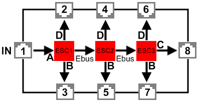
CU1128 - Structure
In order to provide eight EtherCAT connections, the CU1128 has three internal communication ICs (ESCs), which are connected in series internally. For this reason the CU1128 appears as three individual slaves in the EtherCAT configurator, although they are located in one housing. The interrelationship between the internal ESC ports (A, B, C, D) and the descriptions of the connection sockets (1..8) is as follows:
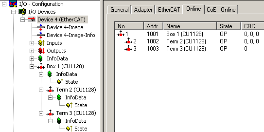
Accordingly, three devices are displayed in the TwinCAT System Manager:
Please note:
- port 1 is always the input for the EtherCAT traffic in the CU1128.
- the other ports 2..7 should be used as outputs.
- it is not permitted to delete subdevices once the CU1128 has been configured.
For differentiation see also EEPROM Update.
CU1128 - Topological configuration
With the CU1128, special attention should be paid to the sequence of the EtherCAT slaves. Since the CU1128 has seven junction ports, drop lines connected to ports must and can be clearly identified in practice. If incorrect information is provided in the configuration (TwinCAT System Manager file *.tsm), the system cannot start.
For each EtherCAT device the System Manager indicates at which Previous Port it is connected, i.e. the name of the connected port (B to D) of the previous slave. This also applies for the internal connections between the ESCs in the CU1128:
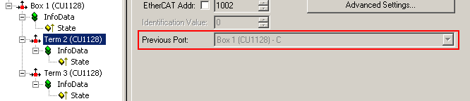
In fig. Previous port of the second ESC in the CU1128, for example, it is stated that the second ESC in the CU1128 “Box 1”, called “Term 2”, is connected to ESC 1 Port C; cf. Fig. CU1128 - diagram. This setting cannot be changed, since it is defined by the CU1128 device.
In general, however, it is changeable if a pluggable coupler, EtherCAT Box or similar is present in the configuration; see Fig. Set the Previous Port for an EK1100. Then,
- drag & drop with the mouse can then be used in the System Manager to set up the general position in the I/O system.
- the previous port in the “fine adjustment” can be selected, if several options are available.
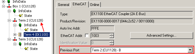
In fig. Set the Previous Port for an EK1100, the coupler “Term 4” is set up as successor to the ESC2 “Term 2”. Both free ports of the ESC2 (B and D, see Fig. CU1128 - diagram) are thus available in the previous port selection of the EK1100; B is selected here.
The System Manager detects whether ports can technically and actually be connected by means of the port property, i.e. Ethernet or E-bus in the ESI/XML device descriptions. The internal connections in the CU1128 are E-bus connections, the eight ports on the other hand are Ethernet, see fig. CU1128 - diagram.
See also notes for configuration setup.