Basic function principles of EtherCAT junctions
Some Beckhoff EtherCAT devices can be used for junctions in the EtherCAT segment. These include EK1122, EK1521, EP1122 or also CU112x. In the following examples only the EK1122 is used. The technical and system characteristics of the other devices are similar.
EtherCAT handling in the slaves
With EtherCAT as fieldbus protocol a wide range of bus topologies can be used: line, star and tree topology, with redundancy support even ring topology. The simplest topology is the line topology, in which each EtherCAT slave passes the data on to the only next slave; see following Fig. EtherCAT line topology.
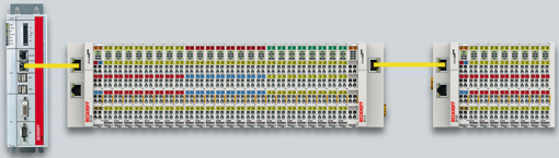
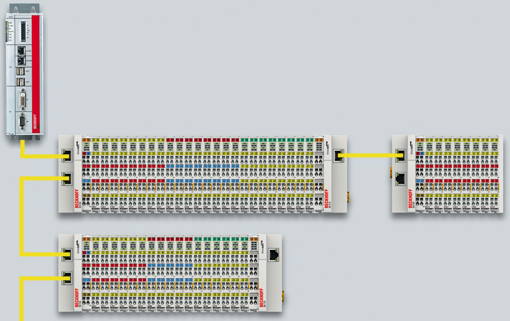
When using, for example, EK1100 EtherCAT Couplers, a junction and thus a type of tree topology is possible; see following Fig. Line topology with extensions.
The basic principle is that internally the Ethernet frame(s) with the EtherCAT protocol data continue to be transported in a logical ring:
- the EtherCAT master sends the frame on the two outgoing lines of the Ethernet cable
- this frame passes each slave once,
- is reversed by the last slave in the logical sequence
- and is returned to the master through each EtherCAT slave via two return lines of the Ethernet cable without further processing.
At short cycle times in the order of 50 µs at 20,000 Ethernet frames are in transit in the EtherCAT system every second, plus acyclic organizational frames. The master awaits the return of the sent frames, which return the device input data to the master, for example. Telegram transfer between slaves is link-based: An EtherCAT slave will only forward a frame if a 'link' signal to the next device is present. Normally it can be assumed that the downstream device correctly processes each EtherCAT telegram and returns or process it at the end.
The crucial factor for forwarding EtherCAT telegrams is that a link signal is reported only from one slave to the next if both slaves are actually ready for real-time participation in data processing. Specifically, this means that an EtherCAT slave should not open the respective Ethernet port until it is ready to receive and forward an Ethernet frame immediately.
A switch or router is usually used for standard Ethernet traffic forwarding. Any collisions or frame losses are compensated through frame repetition in the higher level protocol layers (e.g. TCP). This mode is generally not used for EtherCAT due to the short cycle times and the real-time requirement. Some Ethernet devices such as special switches, for example, report a link to the remote terminal even if they will only be ready for data processing in a few milliseconds. This behavior is particularly noticeable in media converters from 100Base-TX (copper) to 100Base-Fx (optical fiber), which may report a link to the preceding EtherCAT slave even if the optical fiber connection is interrupted, depending on the setting on the copper side.
Fast link detection is therefore a central component of each ESC (EtherCAT slave controller, hardware processing unit for the EtherCAT protocol). According to the EtherCAT specification an ESC can have and control one to four ports. Via an open port it can handle outgoing and incoming Ethernet traffic. The direction of data flow in a fully configured ESC is shown in Fig. Direction of data flow in the ESC – the data in the EtherCAT datagrams are thereby processed only between Ports 0 (A) and 3 (D) in the EtherCAT processing unit.
Ideally link detection and therefore port handling in the ESC should be fast enough that lost frame events are avoided even at 100 µs cycle time. Nevertheless, at least one lost frame can never be ruled out if a connection is disconnected while an Ethernet frame is in transit on this line and in the bus segment downstream of the separation point.
Implementation: EL terminal
A standard EtherCAT slave such as a Beckhoff EL terminal has two ports:
- one for incoming frames (port 0 [A])
- and one for outgoing frames (e.g. port [D]).
The other two ports are internally closed in the ESC. An EtherCAT telegram enters the processing unit via port 0 (A)/top and is forwarded to the next slave via port 3 (D)/left, if a link to this port exists - see green arrows. This is the case if a further EL terminal is connected to the right.
If no link exists, the frame is forwarded to port 1(B) via the purple route. This and port 2 (C) have no link and therefore return the frame to port 0 (A), where the frame leaves via the same Ethernet port through which it arrived at the slave. This is the case if the terminal acts as end terminal.
An EtherCAT device with a single port is therefore only of limited use, since it can only be used as end device.
Implementation: EK1100 EtherCAT Coupler
Three of the four available ports in the EK1100 EtherCAT Coupler are used, thus enabling a connection to the right to terminals and via an RJ45 socket to further couplers; cf. Fig. “Line topology with extensions”. In the EK1100 the processing unit is not used for process data exchange.
Implementation: EK1121-0010 EtherCAT junction, Extended Distance
As in the EK1100, three ESC ports can be connected in these junctions: Two via E-bus within the terminal and one via the RJ45 sockets with Ethernet configuration.
Implementation: EK1122 EtherCAT junction
In the EK1122 all four ESC ports can be connected - two via the internal E-bus and two via the RJ45 sockets with Ethernet configuration. In the TwinCAT System Manager the link statuses of ports 0, 1, 2 and 3 are shown by the online display – they are designated there as ports A, B, C and D; see Fig. “Topology display for interrupted line”.
Implementation: EK1521 / EK1521-0010 / EK1561 EtherCAT junction
As in the EK1100, three ESC ports can be connected in these junctions: Two via E-bus within the terminal and one via the SC socket/versatile link and optical fiber cable/POF line.
Implementation: CU1123-00x0 EtherCAT junction
In the CU1123-00x0 EtherCAT junction three of the four available ports can be connected via the RJ45 sockets.
Implementation: CU1124 EtherCAT junction
In the CU1124 EtherCAT junction all four available ports can be connected via the RJ45 sockets.
Implementation: CU1128 EtherCAT junction
The CU1128 integrates three ESCs, which means eight ports in total are available to users. The three ESCs are interconnected via E-bus.
Example configuration with EK1122
The following section describes the link characteristics under TwinCAT and its representation in the System Manager.
The TwinCAT online topology shows the wiring scheme, see Fig. Online Topology. The EK1122 is selected, so that further information is shown. The green bars above the slaves indicate the correct RUN state in all slaves.
An error is now generated by disconnecting the connection between the upper RJ45 socket (X1) and the EL3102 device. Within a few µs the ESC in the EK1122 detects the lost link and automatically closes the affected port. This has the effect that the next incoming EtherCAT telegram is immediately forwarded to port D (port 3) and the EL4732. The link is thus missing here and the System Manager marks this in the online display; see following Fig. Example configuration with interrupted cable.
The System Manager messages can be interpreted as follows:
- Address 1002 - EK1122: “OP LNK:MIS D”: The slave is in OP state, although a link is missing at port D (3) that should be present according to the configuration
- Address 1003 - EK1100: “INIT NO_COMM”: Since communication with this slave is interrupted its state is shown as INIT
- Address 1004 - EL3104: ditto
 | Logger output The logger output can be displayed in the lower part of the System Manager (Display → Show Logger Output). This may be helpful for diagnostic purposes (for link interruptions and other situations). |
In the topology display any slaves affected by interruption are shown with a red border, see the following Fig. Topology display for interrupted line.
In Fig. “Example configuration” and Fig. “Example configuration with interrupted cable” note the display of acyclic frames, see the following Fig. Comparison of the frame displays in the System Manager.
The image on the left shows a small number (2) of acyclic frames sent by the master during the respective second - all slaves are operating properly. The image on the right shows a significant increase (currently 77 acyclic frames/sec): The EtherCAT master has quickly detected that not all slaves are properly taking part in the data exchange. Once the master has located the fault, it continuously tries to restore the connection.
Reconnection
Once the connection has been restored, the EK1122 reports to the master that a link is present again at port D (3). The EtherCAT master will then make its process data available again for this section. One the preparations are complete, it will instruct the EK1122 to re-open port D (3) for regular data exchange. Cyclic and acyclic data traffic with the other EtherCAT slaves continues normally.
| External access to EtherCAT diagnostics The system offers a wide range of options for accessing status and diagnostic information and EtherCAT master functions from the PLC. Almost all information displayed by the System Manager online can also be retrieved via ADS (see figures on this page). System Manager functions can also be triggered via PLC or ADS. Please refer to the relevant sections in the Beckhoff Information System and the notes on EtherCAT diagnostics. |