Diagnostic LEDs
BK9050
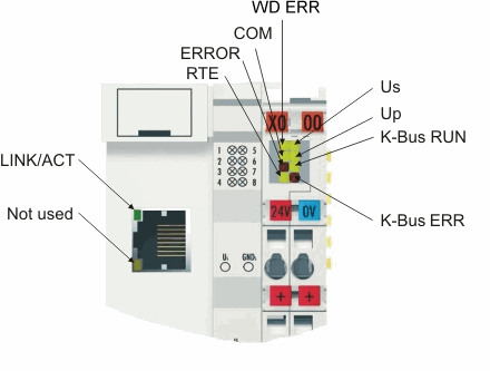
LEDs for power supply diagnostics
|
LED (Power LEDs) |
Meaning |
|---|---|
|
Us |
off: Bus Coupler has no voltage 24 VDC |
|
Up |
off: No 24 VDC power supply connected to the power contacts |
LEDs for K-bus diagnostics
|
LED (K-bus) |
Meaning |
|---|---|
|
K-bus RUN |
on or flashing: K-bus running |
|
K-bus ERR |
flashing: (see error code) |
LEDs for Ethernet diagnosis
|
LED (Ethernet) |
Meaning |
|---|---|
|
WD ERR |
on: Watchdog error |
|
COM |
on or flashing: communication with controller |
|
ERROR |
flashing: DHCP or BootP active. Waiting for an IP address |
|
RTE |
on: hard real-time with TC is switched on. No ADS communication is possible at the same time. All TCP, UPD and ICMP telegrams (e.g. ping) remain unanswered. |
|
LINK/ACT |
on: LINK present |
Error code for K-bus diagnosis
|
Error |
Error |
Description |
Remedy |
|---|---|---|---|
|
- |
flashing continuously |
EMC problems |
|
|
1 |
0 |
EEPROM checksum error |
Enter factory settings with the KS2000 configuration software |
|
1 |
Code buffer overflow |
Insert fewer Bus Terminals. Too many entries in the table for the programmed configuration | |
|
2 |
Unknown data type |
Software update required for the Bus Coupler | |
|
2 |
- |
Reserve |
- |
|
3 |
0 |
K-bus command error |
|
|
4 |
0 |
K-bus data error, break behind the Bus Coupler |
Check whether the n+1 Bus Terminal is correctly connected; replace if necessary. |
|
n |
Break behind Bus Terminal n |
Check whether the Bus End Terminal KL9010 is connected. | |
|
5 |
n |
K-bus error in register communication with Bus Terminal n |
Exchange the nth bus terminal |
|
6 |
0 |
Error at initialization |
Exchange Bus Coupler |
|
1 |
Internal data error |
Perform a hardware reset on the Bus Coupler (switch off and on again) | |
|
2 |
IP address already exists |
Check the IP address; the coupler has already found its set IP address in the network | |
|
4 |
BootP invalid DIP switch setting |
With BootP the DIP switches 1-8 must be all On or all Off | |
|
7 |
0 |
Note: cycle time was exceeded |
Warning: the set cycle time was exceeded. This indication (flashing LEDs) can only be cleared by booting the Bus Coupler again. |
|
9 |
0 |
Checksum error in Flash program |
Transmit program to the BC again |
|
1 |
Incorrect or faulty library implemented |
Remove the faulty library | |
|
10 |
n |
Bus Terminal n is not consistent with the configuration that existed when the boot project was created |
Check the nth Bus Terminal. The boot project must be deleted if the insertion of an nth Bus Terminal is intentional |
|
14 |
n |
nth Bus Terminal has the wrong format |
Start the Bus Coupler again, and if the error occurs again then exchange the Bus Terminal |
|
15 |
n |
Number of Bus Terminals is no longer correct |
Start the Bus Coupler again. If the error occurs again, restore the manufacturers setting using the KS2000 configuration software |
|
16 |
n |
Length of the K-bus data is no longer correct |
Start the Bus Coupler again. If the error occurs again, restore the manufacturers setting using the KS2000 configuration software |