Diagnostic LEDs
The BC9191 and BC9191-0100 have LEDs for status display.
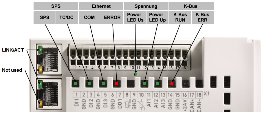
Diagnostic LEDs BC9191 and BC9191-0100 up to HW 4
Diagnostic LEDs BC9191 and BC9191-0100 from HW 5

LEDs for PLC diagnostics
LED | Meaning |
|---|---|
PLC | on - PLC running, flashing - cycle time exceeded, off - cycle time permanently exceeded or PLC stopped |
TC/DC | on - TwinCAT configuration active, off - Default configuration active, flashing TwinCAT configuration faulty |
LEDs for Ethernet diagnostics
LED | Meaning |
|---|---|
LINK/ACT (RJ45) | on - LINK available, flashing - LINK available and communication |
COM | Communication with controller available |
ERROR | flashing - DHCP or BootP active. Waiting for an IP address. short flashing - the source code of the PLC program is loaded and is being checked. No boot project can be created during this check time. |
LEDs for power supply diagnostics
LED | Meaning |
|---|---|
Power LED Vs | on - internal power supply 5 VDC okay (for hardware version 3 and 4 only visible with unplugged connector X1) |
Power LED Vp | on - 24 VDC power supply for external devices okay |
LEDs for K-bus diagnostics
LED | Meaning |
|---|---|
K-bus RUN | on or flashing - K-bus running |
K-bus ERR | flashing (see error code) |
Error code for K-bus diagnostics
Error | Error | Description | Remedy |
|---|---|---|---|
- | flashing continuously | EMC problems |
|
1 | 0 | EEPROM checksum error | Enter factory settings with the KS2000 configuration software |
1 | Code buffer overflow | Insert fewer Bus Terminals. Too many entries in the table for the programmed configuration | |
2 | Unknown data type | Software update required for the BC9191 | |
2 | - | reserve | - |
3 | 0 | K-bus command error |
|
4 | 0 | K-bus data error, break behind the Bus Coupler | Check whether the n+1 Bus Terminal is correctly connected; replace if necessary |
n | Break behind Bus Terminal n | Check whether the KL9010 bus end terminal is connected | |
5 | n | K-bus error in register communication with Bus Terminal n | Exchange the nth Bus Terminal |
6 | 0 | Error at initialization | Exchange Bus Coupler |
1 | Internal data error | Perform a hardware reset on the BC9191 (switch off and on again) | |
2 | DIP switch changed after a software reset | Perform a hardware reset on the BC9191 (switch off and on again) | |
3 | IP address already assigned | Check whether the IP address already exists in the network. | |
7 | 0 | Note: cycle time was exceeded | Warning: the set cycle time was exceeded. This note (flashing of the LED) |
9 | 0 | Checksum error in Flash program | Transmit program to the BC again |
1 | Incorrect or faulty library implemented | Remove the faulty library | |
10 | n | Bus Terminal n is not consistent with the configuration that existed when the boot project was created | Check the nth Bus Terminal. The boot project must be deleted if the insertion of an nth Bus Terminal is intentional. |
14 | n | nth Bus Terminal has the wrong format | Start the BC9191 again, and if the error occurs again then exchange the Bus Terminal. |
15 | n | Number of Bus Terminals is no longer correct | Start the BC9191 again. If the error occurs again, restore the manufacturers setting using the KS2000 configuration software |
16 | n | Length of the K-bus data is no longer correct | Start the Bus Coupler again. If the error occurs again, restore the manufacturers setting using the KS2000 configuration software |