Diagnostic LEDs
After switching on, the Bus Coupler immediately checks the connected configuration. Error-free start-up is indicated when the red I/O ERR LED goes out. If the I/O ERR LED blinks, an error in the area of the terminals is indicated. The error code can be determined from the frequency and number of blinks. This permits rapid rectification of the error.
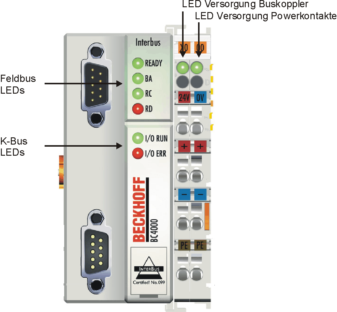
The Bus Coupler has two groups of LEDs for the display of status. The upper group with four LEDs indicates the status of the respective fieldbus. The significance of the fieldbus status LEDs is explained in the appropriate sections of this manual. It corresponds to the usual fieldbus display.
On the upper right hand side of the Bus Couplers are two more green LEDs that indicate the supply voltage. The left hand LED indicates the presence of the 24 V supply for the Bus Coupler. The right hand LED indicates the presence of the supply to the power contacts.
LEDs for power supply diagnostics
LED | Meaning |
|---|---|
Left LED off | Bus Coupler has no power |
Right LED off | No power supply 24 VDC connected at the power contacts |
LEDs for fieldbus diagnosis
The four upper left LEDs indicate the operating status of the INTERBUS communication.
Ready | BA | RC | RD | Meaning | Remedy |
|---|---|---|---|---|---|
on | off | off | off | The Bus Coupler is operational |
|
on | on | on | off | Remote bus active |
|
on | off | on | off | Incoming remote bus connection is established, no communication |
|
on | on | off | on | Remote continuation bus is switched off due to cable fault or by the master | Find cable interruption or short circuit, switch over master |
off | off | off | off | No function, power failure |
|
LEDs for K-bus diagnostics
Two LEDs, the "I/O LEDs", in the area below the fieldbus status LEDs referred to above, serve to indicate the operating status of the Bus Terminals and the connections to these terminals. The green LED lights up in order to indicate fault-free operation. "Error-free" means that the communication with the fieldbus system is also running. The red LED blinks with two different frequencies in order to indicate an error. The error is encoded in the blinks as follows:
Flashing Codes
Fast blinking | Start of the error code |
|---|---|
First slow sequence | Error code |
Second slow sequence | Error code argument |

Error code | Error code argument | Description | Remedy |
|---|---|---|---|
Persistent, continuous flashing |
| EMC problems | - Check power supply for overvoltage or undervoltage peaks |
1 pulse | 0 | EEPROM checksum error | Enter factory settings with the KS2000 configuration software |
1 | Code buffer overflow | Insert fewer Bus Terminals. Too many entries in the table for the programmed configuration | |
2 | Unknown data type | Software update required for the Bus Coupler | |
2 pulses | 0 | Programmed configuration has an incorrect table entry | Check programmed configuration for correctness |
n (n > 0) | Table comparison (Bus Terminal n) | Incorrect table entry | |
3 pulses | 0 | K-bus command error | - No Bus Terminal inserted |
4 pulses | 0 | K-bus data error, break behind the Bus Coupler | Check whether the n+1 Bus Terminal is correctly connected; replace if necessary. |
n | Break behind Bus Terminal n | Check whether the KL9010 Bus End Terminal is connected | |
5 pulses | n | K-bus error in register communication with Bus Terminal n | Exchange the nth Bus Terminal |
6 pulses | 0 ,n (n>0) | Data width more than 32 words at the Bus Coupler | Reduce the fieldbus data |
7 pulses * | 0 | Note: cycle time was exceeded | Warning: the set cycle time was exceeded. This indication (flashing LEDs) can only be cleared by booting the Bus Coupler again. |
9 pulses * | 0 | Checksum error in Flash program | Transmit program to the BC again |
1 | Incorrect or faulty library implemented | Remove the faulty library | |
10 pulses * | n | Bus Terminal n is not consistent with the configuration that existed when the boot project was created | Check the nth Bus Terminal. The boot project must be deleted if the insertion of an nth Bus Terminal is intentional. |
14 pulses | n | nth Bus Terminal has the wrong format | Start the Bus Coupler again, and if the error occurs again then exchange the Bus Terminal |
15 pulses | n | Number of Bus Terminals is no longer correct | Start the Bus Coupler again. If the error occurs again, restore the manufacturers setting using the KS2000 configuration software |
16 pulses | n | Length of the K-bus data is no longer correct | Start the Bus Coupler again. If the error occurs again, restore the manufacturers setting using the KS2000 configuration software |
The number of pulses in the fault segment indicates the position of the last Bus Terminal before the fault. Passive Bus Terminals, such as a power feed terminal without diagnostics, are not included in the count. When the error is rectified, the Bus Coupler does not stop flashing. The Bus Coupler stays in the "Stop" state. The Bus Coupler can only be re-started by switching the power supply off and on again. Insertion and removal of Bus Terminals is only permitted when switched off. The electronics in the Bus Terminals and in the Bus Coupler are protected to a large measure against damage, but incorrect function and damage cannot be ruled out if they are plugged in under power.