First steps with the BC3150
For the following sample, the following hardware and software components are required:
Hardware
- FC310x from firmware 2.0
- BC3150
- KL10x4
- KL20x4
- KL9010
- PROFIBUS cable + cabling material (such as 24 VDC power supply unit etc.)
Software
- TwinCAT 2.9 build 1020 (minimum TwinCAT PLC level)
Example 1: Default Configuration
a.) Open the following link (sample file)
This link contains the System Manager file for the master configuration with the FC310x PROFIBUS card and the BC3150 slaves. Select the correct PCI address for the FC3101
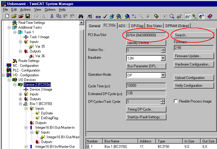
and set PROFIBUS address 11 on the BC3150.
Activate the configuration and start the system. The TwinCAT icon (bottom right on the desktop) should be green. The bus LED of the BC3150 must light up green. Should this not be the case, check the BC3150 address and the physical connection to the PROFIBUS master (terminating resistors etc.).
a.) Open the following link (sample file)
This link is the PLC project for the BC3150. Select the BC3150 under >Online\Selecting the target system<.
Load the project into the controller (>Online\Login<) and Start the program (>Online\Start<). The PLC LED on the BC3150 should now be orange.
Program description
The program increments a value >Profibus_Out_1< as long as the variable Profibus_Input_1 contains the value 0bin. At the same time, the first digital output cycles with approx. 2 Hz. In the System Manager, the variable >Var 36< can be forced to a value unequal zero. This stops the counter, and the first digital output is set to a fixed value of 1bin.