“Touch Probe” function
Operating principle
The “Touch Probe” function detects the position of the drive based on defined input signals. The digital inputs on the ASI8100 can be used for this purpose.
In the tab Process data the necessary inputs and outputs can be added. The abbreviation TP1 stands for Touch Probe 1, and is linked to input 1. The abbreviation TP2 stands for Touch Probe 2, and is linked to input 2.
Each Touch Probe input can only detect edges of one direction at any time (rising or falling). It is not possible to respond to both edges at the same time. There is no dependency between the inputs: A rising edge can be detected at TP1, while a falling edge is detected at TP2.
 | Use the “Tc2_MC2” PLC library The TwinCAT library “Tc2_MC2” contains the “MC_TouchProbe” function block, which simplifies the mapping and handling of the “Touch Probe” function. |
|

The TwinCAT Motion Control PLC library Tc2_MC2 contains function blocks for programming machine applications. It is based on the PLCopen specification for Motion Control function blocks V2.0.
Wiring
The Touch Probe inputs must be wired using single-wire technology (24 V DC).
Configuration
The digital inputs are configured in Drive Manager 2 to use the “Touch probe” function. To describe the function, input 1 (TP1/Probe unit 1) is used as an example here.
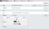
Process image
Checking the checkbox under “digital I/O” automatically adds the necessary process data to the process image of the ASI8100.
 Fig.8: Process image (to follow)
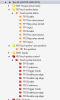 Fig.8: Mapping touch probe status (Inputs)Fig.8: Mapping touch probe control (Outputs)
 TP1 is used here as an example to illustrate the mapping's functionality.
Process data
Status and control word | |
|---|---|
0x1A07 | FB Touch probe status |
0x1607 | FB Touch probe control |
Memory area for the latched position value
The stored position can be read from the PDOs underTP1 pos position(positive edge) andTP1 neg position(negative edge), depending on the edge.
PDOs as a function of the edge | |
|---|---|
0x1A08 | FB Touch probe 1 pos. position |
0x1A09 | FB Touch probe 1 neg. position |
0x1A0A | FB Touch probe 2 pos. position |
0x1A0B | FB Touch probe 2 neg. position |
Latch parameter
Relevant bits | |
|---|---|
TP1 Continuous |
|
TP1 Enable pos edge |
|
TP1 Enable neg edge |
|
TP1 Trigger mode is not relevant to the ASI8100 and has no function.
Handling
- ►SetTP1 Enable to true to enable the touch probe function
- ►Select latch edge:
Set latch to | Bit |
|---|---|
Rising edge | TP1 Enable pos edge = true |
Falling edge | TP1 Enable neg edge = true |
- ►Define the latch interval:
TP1 Continuous | |
|---|---|
Save position at the first event | TP1 Continuous = false |
Save position at each event | TP1 Continuous = true |
Examples
Latching on every rising edge
- ►TP1 Continuous = true
- ►TP1 Enable pos edge = true
Latching on first falling edge
- ►TP1 Enable neg edge = true
- ►TP1 Continuous = false
Cyclic/repeated latching on the first falling edge
To latch onto the first falling edge again, you must disable TP1 Enable and then re-enable it. The position is saved again on the first negative edge.
- ►TP1 Enable neg edge = true
- ►TP1 Continuous = false
- ►TP1 Enable = false
- ►TP1 Enable = true
- ►TP1 Enable neg edge = true
- ►TP1 Continuous = false
- ►…