Control cabinet installation dimensions
Installation in the control cabinet
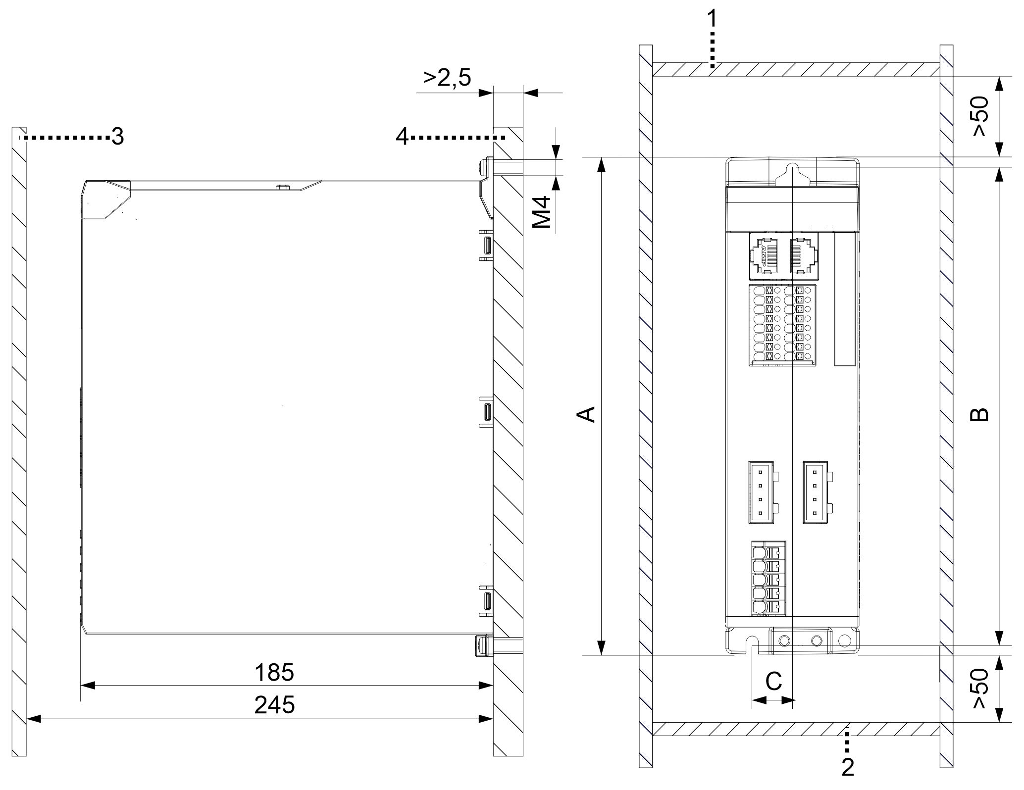
The following illustration contains recommended dimensions that you should observe when mounting the economy variable frequency drive in the control cabinet.
 | The areas, functions and slots shown in the figure may vary depending on the module version and are provided here for clarity. |
Position | Explanation |
|---|---|
1 | Control cabinet top side |
2 | Control cabinet base |
3 | Control cabinet door |
4 | Conductive and galvanized mounting plate |