Konfiguration
- Um einen Planar-Mover anzulegen, muss zunächst eine MC Configuration angelegt werden.
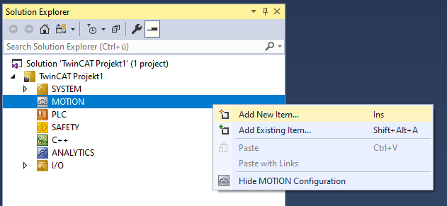
- 1. Wählen Sie MOTION > Add New Item… aus.
- 2. Wählen Sie im folgenden Dialogfenster MC Configuration aus und bestätigen Sie mit OK.
- Sie haben ein MC Project angelegt.
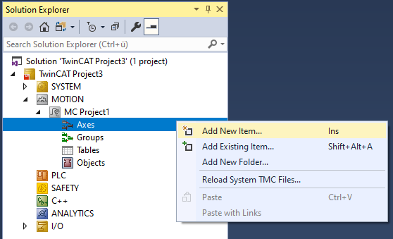
- 3. Wählen Sie im erzeugten MC Project > Axes > Add New Item… aus.
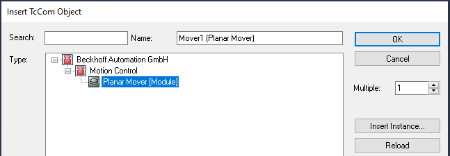
- 4. Legen Sie im folgenden Dialogfenster einen (oder mehrere) Planar-Mover an und bestätigen Sie mit OK.

- Der Planar-Mover ist nun angelegt und kann parametriert werden.
Detailbeschreibung öffnen
- Planar-Mover im Baum auswählen und doppelklicken.
Bedeutung der einzelnen Reiter
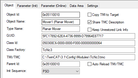
Object: Hier werden allgemeine Informationen (Name, Typ, Id, usw.) dargestellt.
Parameter (Init): Gibt Initialparameter an, die der Anwender verändern kann, um das Verhalten des Movers zu beeinflussen.
 | Parameter (Init) sollte vor dem Parametrieren in den Simulationsmodus ( |
Die Initialparameter sind zunächst so eingestellt, dass der Planar-Mover (fertig verknüpft) mit der Hardware verfahren werden kann. Wenn der Anwender ohne Hardware verfahren möchte, muss der versteckte Parameter „Simulation Mode“ auf TRUE gestellt werden. Im Simulationsmodus sollten die ebenfalls versteckten Parameter „Initial Position“ und „PartOID“ gesetzt werden. Hat der reale Mover keine Standardmaße, so müssen die Parameter „Mover width“ und „Mover height“ angepasst werden.
Ab Version V4.0.6: Die Parameter „Minimal/Maximal position“ dienen dazu, für alle Achsen Genzen zu definieren, die für unabhängige Koordinatenbewegungen (z.B. MoveX oder MoveC Kommandoes) nicht verletzt werden.
Ab Version V4.0.6: Der Parameter „Absolute CRotation threshold“ dient dazu, für die C-Achse festzulegen, wann der Mover in den Befehlsmodus CRotation wechselt. Für den Wert +45° wechselt der Mover in keinem Fall in den Befehlsmodus CRotation.
Für alle Zielpositionen von C-Bewegungen legen die Parameter „C coordinate modulus“ und „C coordinate modulo tolerance window“ im Fall von Modulo Positionierung die Umrechnung in die absolute Zielposition fest. Für Details siehe Modulo Positionierung.
Auch AdoptTrackOrientation ist eine C-Bewegung und wird entsprechend von „C coordinate modulus“ und „C coordinate modulo tolerance window“ beeinflust. Für Details siehe AdoptTrackOrientation.
Die Parameter „PartOID“, „Simulation Mode“ und „Initial Position“ sind alle versteckt und in einer eigenen Gruppierung „Simulation“.
Weitere Parameter sind die „Maximum Dynamic(s)“ und die „Default Dynamic(s)“. Außerdem gibt es noch „Monitoring“-Parameter, die eine Positionsüberwachung des realen Movers aktivieren bzw. parametrieren.
Die Parameter „Maximum dynamic path XY“ und „Default dynamic path XY“ gelten tangential zur Bewegungsrichtung des Movers, z.B. für den Befehlsmodus OnTrack tangential zum Track.
Die koordinatenbasierten Default- und Maximaldynamiken gelten jeweils für die entsprechenden Koordinatenbasierenden Bewegungsbefehle, siehe Beispiel „Planar-Mover anlegen und koordinatenbasiert verfahren (MoveX, MoveY)“ und Beispiel „Planar-Mover mit Hilfsachsen anlegen und verfahren“.
Zusätzlich gelten die Parameter „Maximum dynamic X“ und „Maximum dynamic Y“ für den Befehlsmodus OnTrack. Es hat hierbei nur der Beschleunigungsparameter A einen Effekt. Er wird verwendet, um die maximale radiale Beschleunigung in Kurven einzustellen, wenn die Option „AccelerationLimitedVelocity" im „DynamicsReductionMode" aktiviert ist und auf einem Track verfahren wird. Für Details siehe Limits und Optionen der Bewegungsbefehle.
Der Parameter „Timeout for state machine“ gibt an, wie lange der Mover maximal in Enabling, Disabling oder Resetting verweilt, siehe „Timeouts der Transitionszustände“ in Zustandsdiagramm Planar-Objekte.
Ab Version V3.4.45: Der Parameter „Gap 2D“ gibt den Minimalabstand an, den ein Mover zu anderen Objekten einhält, wenn er mit dynamischer 2D-Kollisionsvermeidung verfahren wird.
Die Parameter „Minimal/Maximal Position“, „Absolute CRotation threshold“, „Default/Maximal Dynamic(s)“, „C coordinate modulus, „C coordinate modulo tolerance window“ und alle „Monitoring“-Parameter (Positionsüberwachung/Timeout/Gap) können im Zustand Enabled des Movers geändert werden. Bisher war dies nur bei Disabled möglich.
Der versteckte Initialparameter „TraceLevel“ beeinflusst, wie viele Informationen protokolliert werden (siehe Protokollierung („Logging/Tracing“)).
Init Parameters
|
Name |
Value |
Unit |
Type |
PTCID |
Comment |
|---|---|---|---|---|---|
|
General | |||||
|
Mover width |
155.0 |
mm |
LREAL |
#x050300B2 |
Width that is used for internal collision checks, can be set for disabled mover. |
|
Mover height |
155.0 |
mm |
LREAL |
#x050300B3 |
Height that is used for internal collision checks, can be set for disabled mover. |
|
Minimal position |
(.x := #Ignore, .y := #Ignore, .z := -1.0, .a := -6.0, .b := -6.0, .c := #Ignore) |
mm, ° |
MoverVector |
#x05093021 |
If set to "#Ignore", no limit is active. Otherwise the soft limit is enforced in independent coordinate mode. |
|
Maximal position |
(.x := #Ignore, .y := #Ignore, .z := 10.0, .a := 6.0, .b := 6.0, .c := #Ignore) |
mm, ° |
MoverVector |
#x05093023 |
If set to "#Ignore", no limit is active. Otherwise the soft limit is enforced in independent coordinate mode. |
|
Absolute CRotation threshold |
45.0 |
|°| |
LREAL |
#x0503023E |
CRotation command mode is active, when the absolute c coordinate setpoint modulo 90° exceeds (or will exceed) this value. |
|
C coordinate modulus |
360.0 |
° |
LREAL |
#x05030107 |
C coordinate modulus. |
|
C coordinate modulo tolerance window |
0.0 |
° |
LREAL |
#x05030108 |
C coordinate modulo tolerance window. |
|
Maximum Dynamics | |||||
|
Maximum dynamic path XY |
(.V := 2000.0, .A := 20000.0, .D := 20000.0, .J := 200000.0) |
mm per s, s², or s³ |
DynamicLimits1D |
#x050300B8 |
Maximum dynamic of the mover in the XY plane along its path. |
|
Maximum dynamic X |
(.V := 2000.0, .A := 20000.0, .D := 20000.0, .J := 200000.0) |
mm per s, s², or s³ |
DynamicLimits1D |
#x05030188 |
Maximum dynamic of the X coordinate of the mover. Only A can be changed (V, D, J must be 1e302). |
|
Maximum dynamic Y |
(.V := 2000.0, .A := 20000.0, .D := 20000.0, .J := 200000.0) |
mm per s, s², or s³ |
DynamicLimits1D |
#x05030189 |
Maximum dynamic of the Y coordinate of the mover. Only A can be changed (V, D, J must be 1e302). |
|
Maximum dynamic C |
(.V := 7000.0, .A := 7000.0, .D := 7000.0, .J := 35000.0) |
° per s, s², or s³ |
DynamicLimits1D |
#x050300B9 |
Maximum dynamic of the C rotation of the mover. |
|
Maximum dynamic Z |
(.V := 10.0, .A := 100.0, .D := 100.0, .J := 1000.0) |
mm per s, s², or s³ |
DynamicLimits1D |
#x050300BA |
Maximum dynamic of the Z coordinate of the mover. |
|
Maximum dynamic A |
(.V := 10.0, .A := 100.0, .D := 100.0, .J := 1000.0) |
° per s, s², or s³ |
DynamicLimits1D |
#x050300CA |
Maximum dynamic of the A rotation of the mover. |
|
Maximum dynamic B |
(.V := 10.0, .A := 100.0, .D := 100.0, .J := 1000.0) |
° per s, s², or s³ |
DynamicLimits1D |
#x050300CB |
Maximum dynamic of the B rotation of the mover. |
|
Default Dynamics | |||||
|
Default dynamic path XY |
(.V := 100.0, .A := 200.0, .D := 200.0, .J := 1000.0) |
mm per s, s², or s³ |
DynamicLimits1D |
#x050300CC |
Default dynamic of the mover in the XY plane along its path. |
|
Default dynamic X |
(.V := 100.0, .A := 200.0, .D := 200.0, .J := 1000.0) |
mm per s, s², or s³ |
DynamicLimits1D |
#x050301D6 |
Default dynamic of the X coordinate of the mover. |
|
Default dynamic Y |
(.V := 100.0, .A := 200.0, .D := 200.0, .J := 1000.0) |
mm per s, s², or s³ |
DynamicLimits1D |
#x050301D7 |
Default dynamic of the Y coordinate of the mover. |
|
Default dynamic C |
(.V := 5.0, .A := 20.0, .D := 20.0, .J := 100.0) |
° per s, s², or s³ |
DynamicLimits1D |
#x050300CD |
Default dynamic of the C rotation of the mover. |
|
Default dynamic Z |
(.V := 5.0, .A := 20.0, .D := 20.0, .J := 100.0) |
mm per s, s², or s³ |
DynamicLimits1D |
#x050300CE |
Default dynamic of the Z coordinate of the mover. |
|
Default dynamic A |
(.V := 5.0, .A := 20.0, .D := 20.0, .J := 100.0) |
° per s, s², or s³ |
DynamicLimits1D |
#x050300CF |
Default dynamic of the A rotation of the mover. |
|
Default dynamic B |
(.V := 5.0, .A := 20.0, .D := 20.0, .J := 100.0) |
° per s, s², or s³ |
DynamicLimits1D |
#x050300D0 |
Default dynamic of the B rotation of the mover. |
|
Monitoring | |||||
|
Position Lag Monitoring Enabled |
TRUE |
|
BOOL |
#x0503011A |
|
|
Maximum Position Lag Value |
(.x := 5.0, .y := 5.0, .z := 1.0, .a := 1.0, .b := 1.0, .c := 1.5) |
mm, ° |
MoverVector |
#x050300BE |
The maximum of the allowed lag for each coordinate. Must be in [0.0,100.0] for each coordinate. |
|
Maximum Position Lag Filter Time |
(.x := 0.02, .y := 0.02, .z := 0.02, .a := 0.02, .b := 0.02, .c := 0.02) |
s |
MoverVector |
#x050300BF |
The maximum of the allowed time for a lag distance violation of each coordinate. Must be in [0.0,10.0] for each coordinate. |
|
Timeout for state machine |
5 |
s |
LREAL |
#x0503D004 |
Timeout for enable, disable, and reset commands of the user in seconds. |
|
Gap 2D |
1 |
mm |
LREAL |
#x050301DD |
Gap the mover tries to keep from other objects in dynamic 2D collision avoidance. |
Parameter (Online): Zeigt den Zustand des Movers während der Laufzeit des Objektes. Die aktuell vorgegebene Position („SetPos“) und reale Position („ActPos“) sowie Zustandsinformationen werden angezeigt.
Der Parameter „External setpoint generation“ zeigt an, ob der Mover (absoluten oder relativen) externen Sollwerten des Nutzers folgt.
Der Parameter „CoordinateSystemOID“ gibt an, in welchem Koordinatensystem SetPos und ActPos angegeben sind, und in welchem Koordinatensystem sich der Mover befindet.
Ab Version V4.0.6: Die Parameter in der Kategorie „Monitoring“ geben detailierte informationen zur Schleppfehlerüberwachung aller sechs Koordinaten.
Ab Version V3.4.60: Die Parameter „On track information“, „Forward blocking neighbours“, „Backward blocking neighbours“ und „Track trail information“ geben spezifische Informationen zum aktuellen Zustand des Movers auf dem Track.
Ab Version V3.4.45: Der Parameter „Blocking object ids“ gibt 0-3 andere Planar-Objekte an, die diesen Mover in der dynamischen 2D-Kollisionsvermeidung blockieren. Die Blockierung kann in den drei Bewegungsrichtungen X, Y und C während des freien Verfahrens erfolgen.
Online Parameters
|
Name |
Unit |
Type |
PTCID |
Comment |
|---|---|---|---|---|
|
General | ||||
|
SetPos |
mm, ° |
MoverVector |
#x050300D2 |
Mover position, read only. |
|
CoordinateSystemOID |
|
OTCID |
#x05030126 |
The coordinate system the mover is on, set and act position are given in this system. |
|
Hardware mover OTCID |
|
OTCID |
#x0503012D |
The object ID of the hardware mover connected to this mover (zero if in simulation mode). |
|
GroupOID |
|
OTCID |
#x050300C3 |
Object id of the PlanarGroup the mover is in, read only. |
|
State |
|
MC_PLANAR_STATE |
#x050300B6 |
State, read only. |
|
Command mode |
|
MC_PLANAR_MOVER_COMMAND_MODE |
#x050300B7 |
Command mode, read only. |
|
ActPos |
|
MoverVector |
#x050300C1 |
Mover hardware position, read only. |
|
External setpoint generation mode |
|
MC_EXTERNAL_SET_POSITION_MODE |
#x050300DB |
Indicates which external setpoint generation mode is active. |
|
Monitoring | ||||
|
Position Lag |
mm, ° |
MoverVector |
#x050301A8 |
This read only online parameter contains the position lag values. |
|
Position Lag Error |
|
MoverVectorBool |
#x050301AB |
This read only online parameter contains the position lag errors. |
|
Minimum Position Lag |
mm, ° |
MoverVector |
#x050301A1 |
This read only online parameter contains the detected minimum position lag values. |
|
Maximum Position Lag |
mm, ° |
MoverVector |
#x050301A2 |
This read only online parameter contains the detected maximum position lag values. |
|
Trigger Minimum/Maximum Position Lag Reset |
|
|
#x050301A3 |
Download parameter to reset stored minimum and maximum position lag values. |
|
Command mode on track | ||||
|
Mover SetPos on track |
|
CDT_MCTOPLC_PLANAR_MOVER_TRACK |
#x050300C2 |
Mover state on track, read only. |
|
On track information |
|
MC_MOVER_ON_TRACK_INFORMATION |
#x05030180 |
General information about the move on the track (target position, gap, etc.). |
|
Forward blocking neighbors |
|
array [1..1] of
|
#x0503012E |
OIDs of neighbors in front of this mover blocking it in standstill on the track. |
|
Backward blocking neighbors |
|
array [1..1] of
|
#x0503012F |
OIDs of neighbors behind this mover blocking it in standstill on the track. |
|
Track trail information |
|
array [1..Unbounded] of
|
#x0503013E |
OIDs of all tracks in this movers track trail. |
|
Miscellaneous | ||||
|
Blocking object ids |
|
array [1..3] of
|
#x050301E3 |
OIDs of all objects blocking this mover in 2D gap control |
Data Area: Zeigt Speicherbereiche, über die der Mover mit anderen Objekten verknüpft ist und Informationen austauscht.
Data Areas
IoToMc
Area No:
4
Type:
InputDst
Symbols
|
Name |
Type |
PTCID |
|---|---|---|
|
STD |
Pointer To CDT_HWTOMC_MOVER |
#x00000000 |
PlcToMc
Area No:
0
Type:
InputDst
Symbols
|
Name |
Type |
PTCID |
|---|---|---|
|
STD |
Pointer To CDT_PLCTOMC_PLANAR_MOVER_STD |
#x0503C006 |
McToIo
Area No:
5
Type:
OutputSrc
Symbols
|
Name |
Type |
PTCID |
|---|---|---|
|
STD |
Pointer To CDT_MCTOHW_MOVER |
#x00000000 |
McToPlc
Area No:
1
Type:
OutputSrc
Symbols
|
Name |
Type |
PTCID |
|---|---|---|
|
STD |
Pointer To CDT_MCTOPLC_PLANAR_MOVER_STD |
#x0503C007 |
|
SET |
Pointer To CDT_MCTOPLC_PLANAR_MOVER_SET |
#x0503C008 |
|
ACT |
Pointer To CDT_MCTOPLC_PLANAR_MOVER_ACT |
#x0503C009 |
|
COORDMODE |
Pointer To CDT_MCTOPLC_PLANAR_MOVER_COORDMODE |
#x0503C00A |
|
SETONTRACK |
Pointer To CDT_MCTOPLC_PLANAR_MOVER_TRACK |
#x0503C003 |
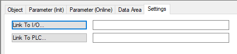
Settings: Hier kann der Anwender Verknüpfungen herstellen. Mit den beiden Buttons „Link To …“ kann der Planar-Mover mit den Movern in der PLC und im Xplanar-Treiber verknüpft werden.