Generating a communication link
Once the configured actual state of the EAP devices has been mapped, this configuration can be modified. Two modifications are illustrated as examples.
(A) Configuring a further communication link
The most convenient method to configure a communication link between two EAP devices is to use the Connector tool from the toolbox (cf. section The Connector tool).
- 1. Select the Connector tool with a mouse click.
- 2. Click on the EAP device object, which is to send the data.
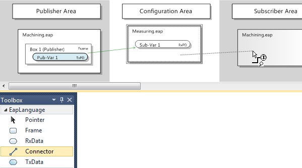
- 1. Then click on the EAP device object, which is to receive the data.
(see illustration above) - A dialog opens, in which the symbol names of the PLC variables are listed, which were imported from the EDC file (see illustration below).
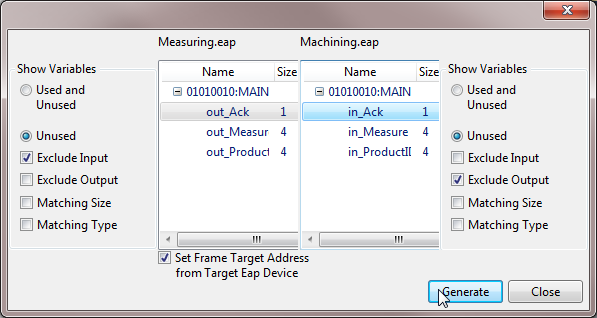
The list on the left shows the symbol names of all output variables of the sender, the list on the right shows the symbol names of all input variables of the receiver.
- 1. In the list on the left select the variable whose values are to be sent.
- 2. In the list on the right select the variable, which is to receive the sent values.
- 3. Use the [Generate] button to generate the communication link.
- Further connections between the two EAP device objects can then be configured, or the dialog can be closed via the [Close] button.
 | The size of the send and receive variables must match. Ensure that the size of the selected send and receive variables is identical. In order to avoid errors during the selection, the Matching Size display filter can be activated on the receiver side or the sender side. When the filter is active, only the symbol names of variables that match the size of the selected variable are displayed. |
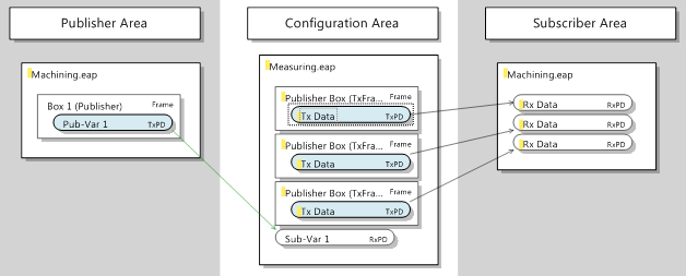
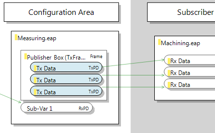
In this example all output variables are successively linked to the corresponding input variables, so that in the end three Publisher boxes, each with a TxData, are configured for the sender and three RxData for the receiver (see illustration).
Once the required configuration is complete, it has to be transferred to the EAP device. This measure is described in section Transferring the new/modified configuration to the EAP devices.
(B) Changing the properties of an existing communication link
The send and receive characteristics of each communication link can be configured more specifically, if required. All options provided by the TwinCAT EAP Configurator for this purposes are explained in section The Properties window. The modification of four commonly modified properties is illustrated as an example.
Configuring a multicast MAC address as destination address
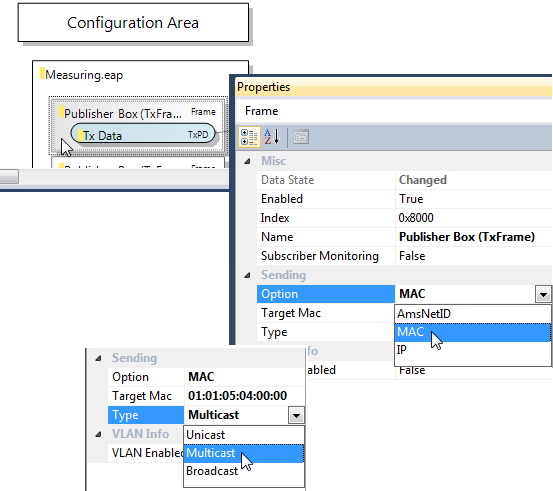
A generated communication link is generally configured such that the variable is addressed to an individual receiver (unicast). However, in some cases it is desirable that the variable reaches several receivers. In this case, the variable has to be sent in a broadcast- or multicast-addressed frame. A multicast configuration is preferable, in order to avoid unnecessary load on other network devices.
To this end, set the property Type to Multicast in the Properties window of the respective Publisher box (TxFrame). The TwinCAT multicast address for EAP devices is then automatically entered as the standard multicast address under the property Target MAC (see illustration).
| Other multicast address If a multicast address is required that differs from the standard multicast address for TwinCAT EAP devices, please refer to section Multicast MAC Address in chapter The RxData. |
Once the configuration has been modified, it has to be transferred to the EAP device. This measure is described in section Transferring the new/modified configuration to the EAP devices.
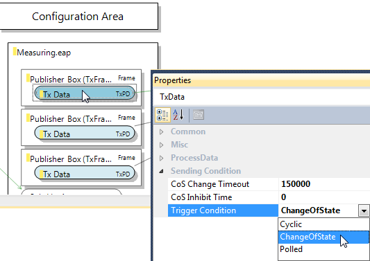
Configuring the send trigger for the condition Change of State
Normally, the property Cyclic is configured for the trigger condition of a TxData. If a variable is only to be sent when its value has changed, the trigger condition must be configured for the property Change of State (CoS). Accordingly, the properties change Timeout Time and Inhibit Time must be defined (see section The TxData). When defining this times, observe the note in section The object dictionary.
In this example the measurement takes 200 ms. Accordingly, the Change Timeout Time is set to 150000 µs for all three TxData of machine M, and the Inhibit Time to 0 µs (see illustration). As a result of this setting, the variables are resent after 150000 µs = 150 ms at most, even if their values have not changed. If the value of a variable changes with each task cycle (e.g. every 10 ms), the variable is sent once in each cycle (due to the Inhibit Time = 0 µs).
Similarly, a timeout value of 1000000 µs = 1000 ms can be configured for the TxData of Machine O. In this example the processing time of Machine O is based on the measured values for Machine M. The measured values vary between 4500 and 5500. Processing in Machine O then takes half the measured value in milliseconds (cf. Project examples). Accordingly, it is sufficient for Machine O to send the request variable every second at most.
Once the configuration has been modified, it has to be transferred to the EAP device. This measure is described in section Transferring the new/modified configuration to the EAP devices.
Moving variables from different frames into one individual frame
In this example it is important that the process variables out_Measure, out_ProductID and out_Ack are consistent for the product to be machined. For this reason these data should always be sent together in a data packet. During the configuration with the aid of the Connector tools, a separate frame was configured for each variable. Now all variables are to be moved to a single frame.
This modification can easily be accomplished in the TwinCAT EAP Configurator:
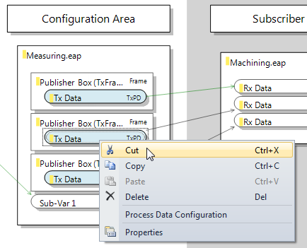
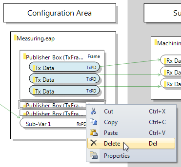
The required commands can be found in the context menus of the respective graphical objects. Alternatively, the familiar keyboard shortcuts ([Ctrl] + [X] for cut, [Ctrl] + [V] for paste and [Delete] for delete) can be used.
- 1. Select the TxData from the second Publisher box and cut it using the [Cut] command (see illustration).
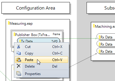
- 1. Then select the first Publisher box and use the [Paste] command to insert the TxData (see illustration).
- Proceed accordingly for the TxData from the third Publisher box.
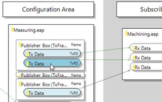
Finally, the two empty Publisher boxes can be deleted by selecting them sequentially and using the [Delete] command (see illustration).
The configuration then looks as shown in the following illustration.
Once the configuration has been modified, it has to be transferred to the EAP device. This measure is described in section Transferring the new/modified configuration to the EAP devices.
Configuring a particular sender NetID as receive filter
By default an RxData is configured such that the sender of a variable is irrelevant for its reception. However, particularly in large networks with many EAP variables, it can be very helpful if receivers can be set to receive variables only from certain senders.
In this example the Local AoE Net ID of the EAP device sending the required variable is entered in the Filter AMS Net ID under the properties of the RxData (see illustration).
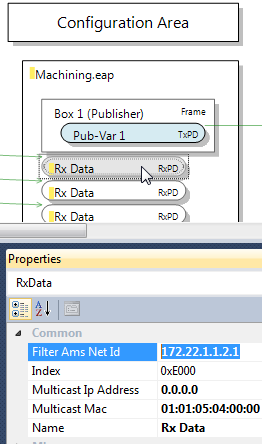
This setting ensures that the EAP variable is only received, if it was sent by the EAP device with the specified NetID.
Once the configuration has been modified, it has to be transferred to the EAP device. This measure is described in section Transferring the new/modified configuration to the EAP devices.