Front side and operating elements

Front side and operating elements 1:
Front PS9011-2440-0000

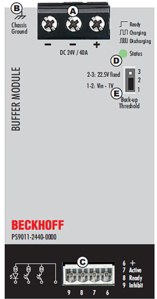
Supply voltage terminals (screw terminals)

Designation (A)

Description

+

Positive supply voltage terminal (1x)

-

Negative (back) supply voltage terminal (2x)

Chassis ground terminal (ring terminal)

Designation (B)

Description

chassis ground

Connection to device upper side with a ring terminal, suitable for an M4 screw.
The connection of the chassis to the ground (earth) is optional and is only necessary for certain applications.

Signal connection (4-pin connector with screw connection)

Designation (C)

Description

6 +
7 Active
8 Ready
9 Inhibit

- "+" – positive switching output
- "Active" signal, for details see chapter Active signal
- "Ready" signal, for details see chapter Ready signal
- "Inhibit" input, for details see chapter Inhibit input

Status LED

Designation (D)

Description

LED green

This green LED shows the following information:
- OFF: capacitors are discharged or the supply voltage is lower than 22 V.
- ON: capacitors are fully charged
- Slow flashing (1.25 Hz): capacitors are being charged.
- Fast flashing (10 Hz): the capacitors are discharging.

Backup threshold value jumper

Designation (E)

Description

Backup
threshold

- Option 1: Fixed mode (jumper in position 2-3): the device switches to buffer mode as soon as the voltage drops below 22.5 V.
- Option 2: Variable mode (jumper in position 1-2): the device switches to buffer mode when the input voltage drops by 1 V. Voltage changes slower than 0.54 V/s are ignored if the voltage is above 22.5 V. Buffering begins immediately below 22.5 V.
For further details, refer also to the chapter Selection of the backup threshold voltage