Operation modes
The operating mode of the terminal is set via feature register R32.
PWM mode
2 channels can be operated in the PWMx modes. Note that the operating mode and the cycle duration for both channels are identical.
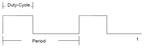
PWMH
In PWM mode, the ratio of duty cycle to cycle duration is determined by the process data.
100 % duty cycle corresponds to process record 0x7FFF. The cycle duration can be specified during operation via register R2. It is loaded after a system start-up from register R35 (SEEROM) and entered into R2.
The frequency range covers 245 Hz to 20 kHz (0xFA0 in R2 corresponds to 250 Hz) with a resolution of 10 bit at 245 Hz, 976 Hz and 3.9 kHz.
PWML
In PWM mode, the ratio of duty cycle to cycle duration is determined by the process data. 100 % duty cycle corresponds to process record 0x7FFF (32767). The cycle duration can be specified during operation via register R2. It is loaded after a system start-up from register R35 (SEEROM) and entered into R2.
The frequency range is from 2 Hz to 250 Hz (250 Hz corresponds to 0x01F4 in R2).
Frq-Cnt PWM mode
The frequency is specified in 2 Hz per digit via the process output data of the control. The controller receives the number of periods that are output by the terminal as process input data. In this operating mode, the count direction is determined via the sign of the output data. 2 Hz corresponds to the value 0x0001, -2 Hz corresponds to the value 0xFFFF (signed integer). The frequency range is 2 Hz to 2 kHz. The pulses are issued at output A1, the count direction at output A2. Down corresponds to signal level GND, up corresponds to signal level Vcc (24 V).
With rising edge of control bit 0 the counter is set to the value of the output data (control byte in process data mode, i.e. bit 7=0).
The pulse width ratio is specified via R36.
Frq-Cnt pulse mode
The frequency is specified in 2 Hz per digit via the process output data of the control. The controller receives the number of pulses that are output by the terminal as process input data. In this operating mode, the count direction is determined via the sign of the output data. 2 Hz corresponds to the value 0x0001, -2 Hz corresponds to the value 0xFFFF (signed integer). The pulses are issued at output A1, the count direction at output A2. Down corresponds to signal level GND, up corresponds to signal level Vcc.
The frequency range is 2 Hz to 2 kHz.
With rising edge of control bit 0 the counter is set to the value of the output data. (Control byte in process data mode, i.e. bit7=0).
The pulse width is fixed for all frequencies and is specified via R37.
Cnt-Cnt PWM mode
The number of pulses is specified via the process output data. The controller receives the number of output periods as process input data. The pulse width ratio is specified via R36, the cycle duration via R35. The output is started with a positive edge of control bit 0. It can be triggered with each additional edge. The pulses are issued at output A1, output A2 can be set via control bit 2. In status bit 0 the controller receives the transfer and the simultaneous start of the pulse output as status information. Status bit 1 remains set as long as the output is active and status bit 2 returns the status of channel 1.