LEDs
Overview
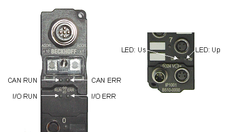
The CANopen Fieldbus Box has two groups of LEDs for the display of status. The upper group (fieldbus LEDs) indicates the status of the fieldbus.
The two I/O LEDs (I/O RUN, I/O ERR) are located under the fieldbus status LEDs. The purpose of these is to display the operating state of the local, decentralised I/Os, and the connection to them via IP-Link.
Beneath these there are two further green LEDs to display the supply voltage. The left hand LED (Us) indicates the presence of the 24 V supply for the Fieldbus Box. With some types of signal, this supply voltage is also used to feed the sensor elements (see I/O documentation). The right hand LED (Up) indicates the presence of the supply to the outputs.
Fieldbus LEDs
Fieldbus LEDs
The upper two LEDs indicate the operating state of the CANopen communication. The CAN-ERR LED here provides an indication of the physical state of the bus as well as of protocol errors. The RUN LED indicates the CANopen status of the bus node.
The behaviour of the LEDs accords with CANopen recommendation DRP303-3 from CAN in Automation.
CAN-ERR blink code
CAN ERR | Meaning |
|---|---|
off | CAN bus has no errors |
Fast blinking | Automatic baud rate detection has still not found a valid baud rate. Not enough telegrams on the bus yet. |
1 x flash | CAN warning limit exceeded. There are too many error frames on the bus. Please check the wiring (e.g. termination resistors, screens, conductor length, stubs). Other possible causes for exceeding the warning limit: there are no other participating devices in the network (occurs, for instance, when the first node is started). |
2 x flashes | The guarding or heartbeat monitor has asserted, because either guarding telegrams or heartbeat telegrams are no longer being received. |
3 x flashes | A synchronisation error has occurred. No sync. telegrams have been received during the set monitoring time (object 0x1006 x 1.5). The bus node is pre-operational (PDOs switched off), and the outputs are in the error state. |
4 x flashes | Event timer error: The Bus Coupler has not received an RxPDO within the set event time (0x1400ff sub-index 5). The bus node is pre-operational (PDOs switched off), and the outputs are in the error state. |
RUN blink code
RUN | Meaning |
|---|---|
off | Firmware status < C0: The state of the bus node is STOPPED. No communication is possible with SDO or PDO. |
Fast blinking | Automatic baud rate detection has still not found a valid baud rate. Not enough telegrams on the bus yet. |
1 x flash (approx. 200ms on, 1s off) | The state of the bus node is STOPPED. No communication is possible with SDO or PDO. |
Alternate flashing | The state of the bus node is PRE-OPERATIONAL. The node has not yet started. |
on | The state of the bus node is OPERATIONAL. |
I/O LEDs
I/O LEDs
Two LEDs, the I/O LEDs, indicate the operational state of the I/O and the connection to these via IP-Link. The green LED (I/O RUN) lights up in order to indicate fault-free operation. The red LED (I/O ERR) flashes with two different frequencies in order to indicate an error. The errors are displayed in the blink code in the following way:
1. Fast blinking: Start of the error code
2. First slow sequence: Error code
3. Second slow sequence: Error code argument or location of the error

Start of the Error Code Error code Error code argument
Compact Box (without IP-Link connection):
The I/O LEDs indicate the state of the internal communication with the sensor circuit board.
LED green | LED red* | Description | Remedy | |
|---|---|---|---|---|
off | off | No local data exchange | Correct the CANopen communication error, and switch the Compact Box into the pre-operational or operational state. | |
off | 1 | 0 | EEPROM checksum error | Set manufacturer’s setting with the KS2000 software |
on | off | Module is exchanging data | No error | |
* Red LED, left-hand column: error code; right-hand column: error code argument
Coupler Box (with IP-Link connection)
The I/O LEDs indicate the state of the IP-Link connection. IP-Link errors are most often the result of inappropriate handling of the optical fibre.
LED green | LED red* | Description | Remedy | |
|---|---|---|---|---|
off | off | No data exchange | Module in synchronous mode or - activate Profibus cyclic data | |
off | 1 | 0 | EEPROM checksum error | Set manufacturer’s setting with the KS2000 software |
off | 2 | Reserve | - | |
off | 3 | n | Break location has been recognised | nth module before the master's receiver |
off | 4 | n | Too many faulty telegrams have been detected | The optical fibre wiring in front of the nth extension module should be checked |
off | 5 | n | Register access to complex modules has failed | Check the nth module |
off | 11 | n | Complex module working incorrectly | Exchange the nth module |
off | 12 | n | More than 120 modules in the ring | Connect fewer modules |
off | 13 | n | nth module unknown | Firmware update required |
on | off | Module is in data exchange | No error | |
* Red LED, left-hand column: error code; right hand column: error code argument or location of error.
LED green | LED red | Description |
|---|---|---|
off | on | No data is being received over the IP-Link |
off | blinks, flickers | Faulty IP-Link protocols are being received (very poor data connection) |
blinks, flickers | blinks, flickers | Faulty IP-Link protocols are being received (poor data connection), does not necessarily lead to an error |
blinks, flickers, on | off | IP-Link protocols are being received, no error |