IO-Link master connection
IO-Link interface
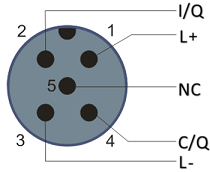
The IO-Link specification defines various IO-Link pin assignment, which are described in the following section.
The switching and communication line is marked with (C/Q).
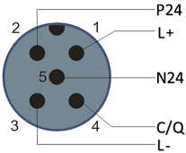
Port Class A (type A): The function of pin 2 and pin 5 is not preset. The vendor can assign an additional digital channel to pin 2. Port Class B (type B): pin 2 and pin 5 are used for an additional power supply. The information regarding the pin assignment of your module can be found in the chapter "Introduction".
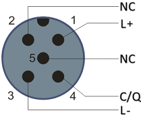
In the case of Class A modules an additional digital input or output (I/Q) can be connected to Pin 2.
Port Class B (type B): For devices with higher current demand, an additional power supply is provided via pin 2 and pin 5.
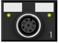
The IO-Link master (EP622x-xxxx) has an A-coded M12 socket for the outgoing IO-Link connection.
Wire colors
The wire colors of the IO-Link cable with corresponding pin assignment of the IO-Link connector:
Pin | Wire color |
|---|---|
1 | brown |
2 | white |
3 | blue |
4 | black |
5 | grey |
IO-Link cable
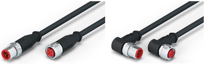
The cables available from Beckhoff for the IO-Link system can be found in the chapter .
 | IO-Link cable A 3-core IO-Link cable may be sufficient for Class A masters/devices from Beckhoff. A Class B master/device requires a 5-wire IO-Link cable. |