Data Logging
Overview
With the data logging the continuous logging of all relevant EP9224 data can be started.
These data are written to a 40-line ring buffer. In the case of the EP9224-0037 the memory is 25 lines..
On the first error the recording is stopped so that the data can be evaluated after an error or during normal operation.
In the event of an error, data are still written for a few cycles. The switching-off of a channel is indicated by OFF.
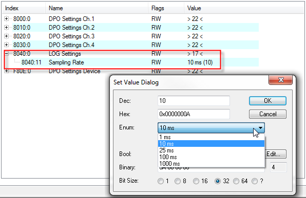
The writing rate or scanning rate is 10 ms in the factory setting. The value can be adjusted from 1 ms to 1000 ms in the CoE.
Setting the sampling rate via CoE object 8040:11
Starting the logger
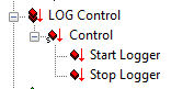
The logger is started/stopped via the process data
- Start logger and
- Stop logger
These must be enabled via the PDO mapping 0x1610 (see PDO settings).
DPO LOG Control
The log file is written when stopping the logger or in the case of an error.
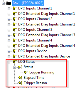
The state of the logger can be tracked in the PDO input area.
To do this it is necessary to activate the PDO 0x1A10 (see PDO settings).
DPO LOG Status
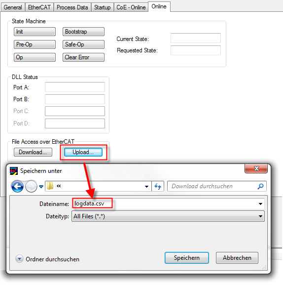
Upload the file from the EP9224
The EP9224 creates the file, giving it the name logdata.csv. This cannot be changed.
When uploading, for example, it must be specified accordingly in TwinCAT.
Structure of the logging file: logdata.csv
The data are saved in the CSV format, so that simple viewing with EXCEL or a corresponding interpretation is possible.
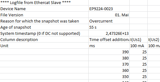
Header
Field | Description |
|---|---|
Device Name | Name of the module |
File Version | Version number |
Reason for which the snapshot was taken | Reason for stopping the data logger |
Age of snapshot | time elapsed from stopping the data logger until the upload |
System timestamp (0 if DC not supported) | current timestamp when uploading |
Columns
Type | Description |
|---|---|
Time offset additional to snapshot age | The age of the measured values in the row in relation to the stopping of the data logger (0 = stop, > 0 older values) in ms |
I(U...) | present current values of the channels Us / Up 1 - 4 in 100 mA |
Internal Temperature | internal module temperature in °C |
Us / Up | Input voltage Us and Up at the 7/8" input in V |
Sum Current Us / Up | Sum current of Us and Up in A |
I²t(U...) | virtual overload, incremented or decremented depending on the nominal current
|
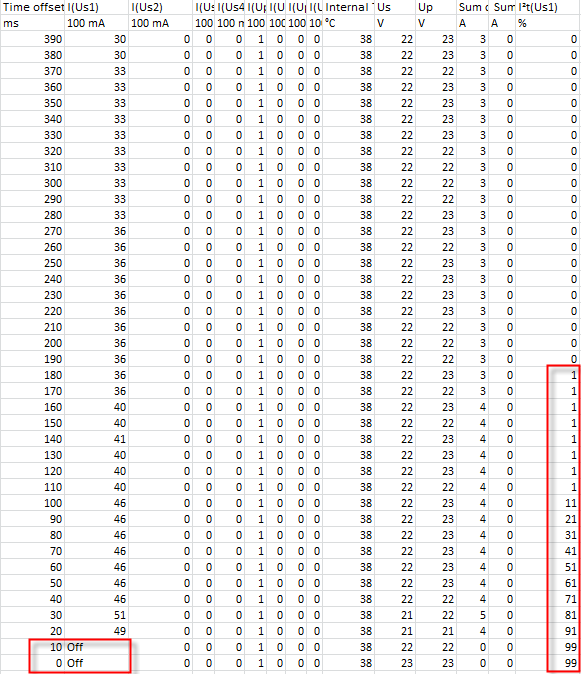
Example: slow exceeding of the current (simulation with potentiometer)
logdata.csv (zip)
Description:
- EP9224: Setting the Us channel to a nominal current of 1500 mA
- Continuous increase of the current on channel1 Us within the recorded range of 3.0 A to 4.9 A, then switch-off takes place.
- Overcurrent begins from 180 ms
- 100% overload reached (99), channel is switched off
- the module now waits for an error correction or an active reset of the error