NC settings
(Master TwinCAT 2.11 R3)
The data given here serve as an example for a servomotor type AM8122-0F20-0000 from Beckhoff Automation. For other motors the values may vary, depending on the application.
Table of contents |
|---|
Definition of the unit |
Several important parameters are required for the commissioning with the NC. These should be set as follows before commissioning. A fundamental factor for setting the following parameters is the unit in which the NC is set to operate. For the following parameters it was assumed that one revolution corresponds to 360°.
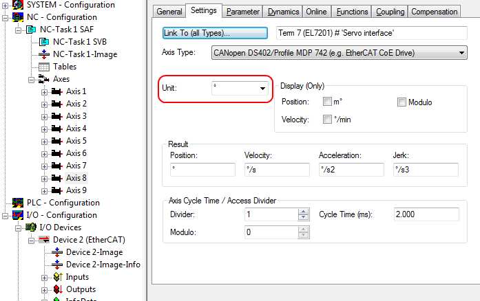
Definition of the unit
The unit can be defined in the Settings tab for the axis.
Selecting the maximum velocity
The maximum permitted velocity is calculated based on the maximum motor speed (name plate) and the distance, in this case in relation to 360° per second.
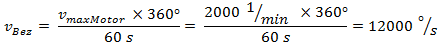
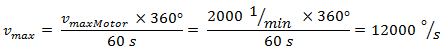
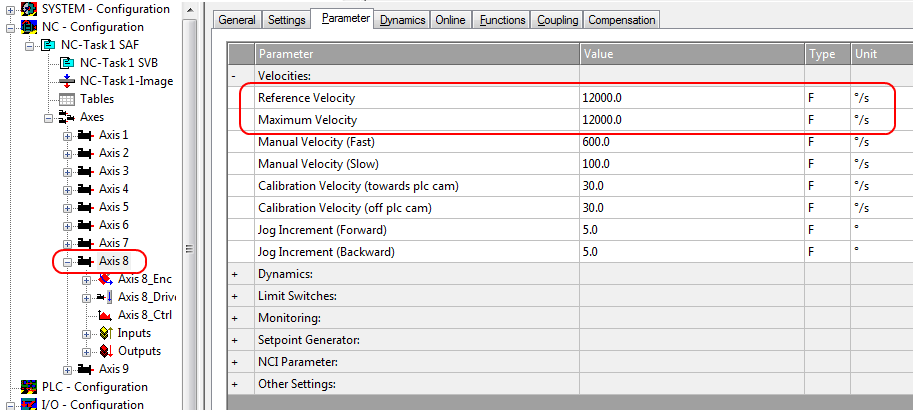
The reference velocity matches the maximum permitted velocity.
Below that separate values for the maximum and minimum velocity for manual NC mode can be set.
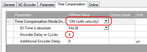
Dead time compensation
The dead time compensation can be adjusted on the Time Compensation tab of Axis1_ENC.
It should theoretically be 3 cycles of the NC cycle time, although in practice 4 cycles are preferable.
Therefore, the settings of the parameters Time Compensation Mode Encoder should be ‚ON (with velocity)‘ and Encoder Delay in Cycles ‘4’.
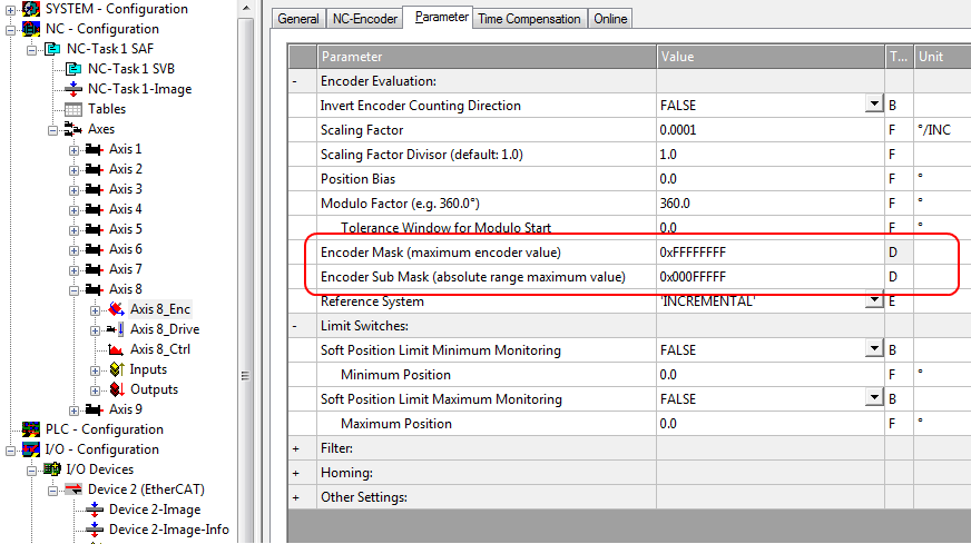
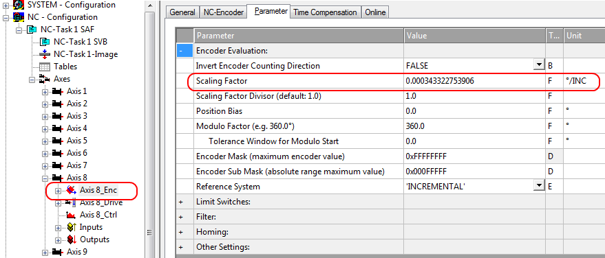
Setting the encoder mask
The maximum values for the encoder mask can be set in the Parameter tab for the Axis1_ENC encoder settings. EP7211 provides a maximum of 32 bits for the encoder.
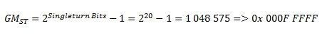
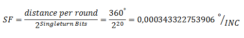
The parameter Encoder Mask (maximum encoder value) can be used to set the maximum number of available bits. By default this is set to 0xFFFF FFFF, which corresponds to 32 bits (20 single-turn bits and 12 multi-turn bits). The calculation is based on the following equation.

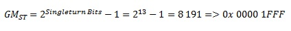
The parameter Encoder Sub Mask (absolute range maximum value) indicates how many bits of the maximum encoder value are single-turn bits. The default setting is 20 (and therefore 12 multi-turn bits). The calculation is based on the following equation.
Further calculation example with 13 single-turn bits and 8 multi-turn bits.

Scaling factor
The scaling factor can be changed by selecting "Axis 1_Enc" and tab Parameter in the NC (see Setting the Scaling Factor). The value can be calculated with the formulas specified below. The calculation is based on the assumption that one revolution corresponds to 360°.
The number of single-turn bits is taken into account in the calculation of the scaling factor. As indicated above, the default setting for EP7211 is 20 single-turn bits. This value is also used for calculating the scaling factor. If the single-turn bit value is changed, the scaling factor must be adjusted.
Calculation of the scaling factor
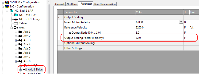
Scaling output
Enter the value 32 in the Parameter tab for the drive settings under Output Scaling (Velocity).
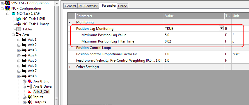
Position lag monitoring
The position lag monitoring function checks whether the current position lag of an axis has exceeded the limit value. The position lag is the difference between the set value (control value) and the actual value reported back. If the box parameters are set inadequately, the position lag monitoring function may report an error when the axis is moved. During commissioning it may therefore be advisable to increase the limits of the Position lag monitoring slightly.
Note | |
Damage to equipment, machines and peripheral components possible! Setting the position lag monitoring parameters too high may result in damage to equipment, machines and peripheral components. |
Commissioning the motor with the NC
- Once the parameters are set, the motor is basically ready for operation. Individual further parameters have to be adapted to the respective application.
- To commission the axis, activate the configuration (Ctrl+Shift+F4), select the axis, select tab Online and enable the axis under Set.
- Set all tick marks and set Override to 100% (see Fig. Enabling an axis). The axis can then be moved.
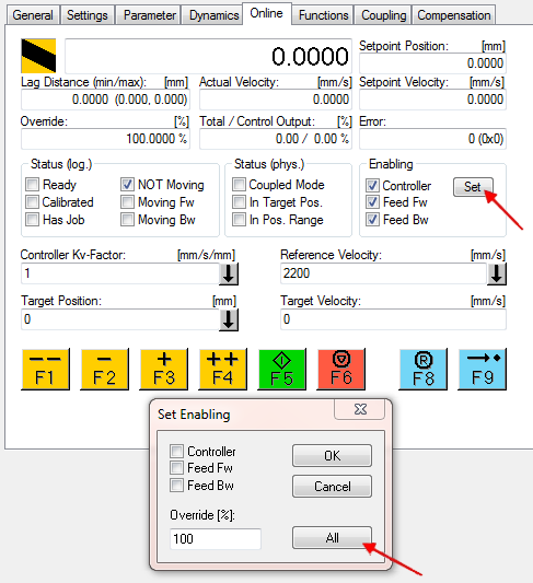
You can now move the axis with the function keys F1, F2 (Backward) or F3, F4 (Forward).
You can adjust the Kv factor in order to approach a suitable factor. Set the value to 0 initially in order to set the correct reference velocity. For calculating the reference velocity please refer to section "Selecting the maximum velocity". The calculation provides a relatively precise value, although the value may have to be corrected slightly. To this end move the motor with a Kv factor of 0 until the actual velocity matches the setpoint velocity.
Alternatively you can control the axis via the Functions tab. An example is provided below.
- Select as Reversing Sequence as the start type.
- Enter the required Target Position2, e.g. 12000°.
- Enter the required Target Velocity, e.g. 12000°/s.
- Enter the required Target Position1, e.g. 0°.
- Enter the required Idle Time, e.g. 2 s.
- Select Start.
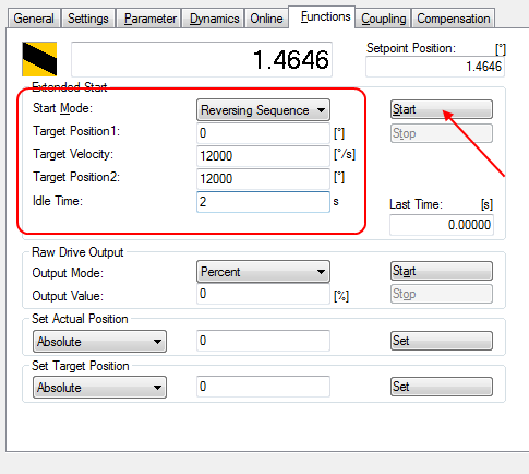
The motor now turns to position 2, remains there for 2 seconds and returns to position 1. This is repeated until Stop is pressed.