Analog voltage outputs (M12)
Analog outputs, -10 to +10 V
The actuator is connected via “Output +/-“ and “Output GND”. The actuator can optionally be operated/supplied with 24 VDC.
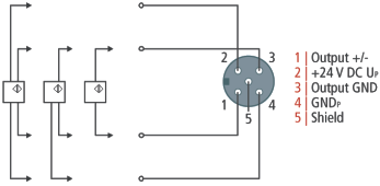
The ground potentials "Output GND" (pin 3) and "GNDP" (pin 4) are galvanically isolated. If the actuator requires a supply voltage and has only one ground connection, connect pin 3 and pin 4 with a bridge.
LED indicators - meanings
There is a green Run LED and a red Error LED for each channel. The green Run LED is lit when data are transferred to the D/A converter. The red Error LED indicates that there is an error (open circuit, measured value outside the range).
Correct function is indicated if the green Run LED is on and the red Error is off.