TwinCAT 3 procedure
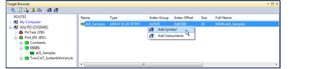
From TwinCAT 3.1 build 4012 and using the revision as below specified in the configuration, the integrated ScopeView recognizes in its variable browser that the oversampling data is an array package and activates ForceOversampling automatically. The array as a whole must be selected using AddSymbol (see description in the next section).The extended PDO name provides the basis for this. Since a specific revision of the respective terminal ScopeView is able to detect the array type of a set of variables autonomous.
Terminal | Revision |
|---|---|
EL4732 | all |
EL4712 | all |
EL3783 | EL3783-0000-0017 |
EL3773 | EL3773-0000-0019 |
EL3751 | all |
EL3742 | all |
EL3702 | all |
EL3632 | all |
EL2262 | all |
EL1262-0050 | all |
EL1262 | all |
EP3632-0001 | all |
EPP3632-0001 | all |
Recording a PLC Variable with the TwinCAT 3 – ScopeView
By a precondition of an already created TwinCAT 3 – project and a connected PLC with an oversampling able terminal/box within the configuration it will be illustrated how an oversampling variable can be represented by the Scope (as a standard part of the TwinCAT 3 environment). This will be explained by means of several steps based on an example project “SCOPE_with_Oversampling“ as a standard PLC project.
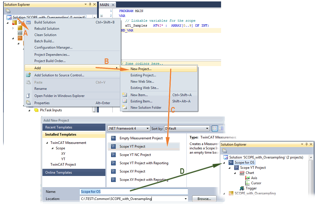
Step 1: Adding a project „Scope YT“
The example project “SCOPE_with_Oversampling“ has to be added a TwinCAT Measurement – project “Scope YT project” (C) by right click (A) and selection (B) “Add” → “New Project..”. Then “Scope for OS” will be entered as name. The new project just appears within the solution explorer (D).
Step 2a: Creation of a PLC variable within a POU
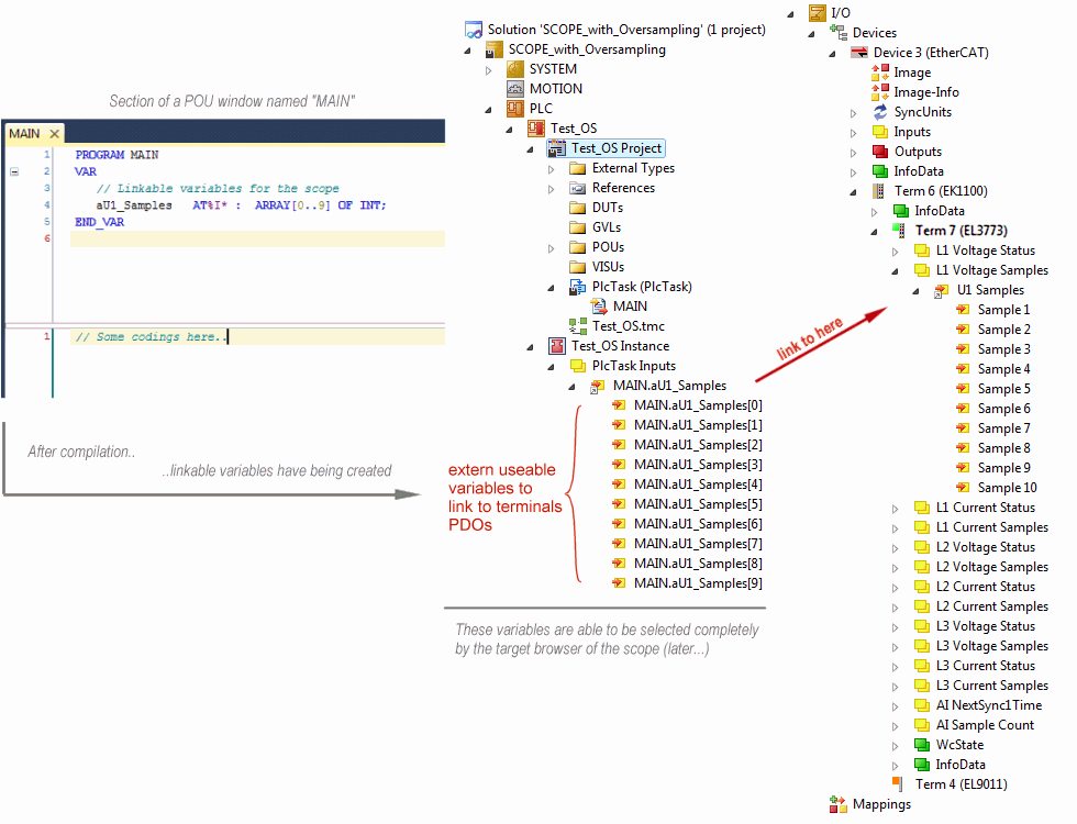
Within the TwinCAT 3 development environment an input variable as an array with respective amount than is given by the oversampling factor have to be defined at first how it’s illustrated in an example for the POU “MAIN” and an oversampling factor 10 with structured text (ST) as follows:
PROGRAM MAIN
VAR
   aU1_Samples AT%I* : ARRAY[0..9] OF INT;
END_VAR
The identification “AT%I*” stands for swapping out this array variable to link it with the process data objects (PDOs) of a terminal/box later. Notice that at least the number of elements has to be the same as the oversampling factor so that the indices can be set from 0 to 9 also. As soon as the compiling procedure was started and ended successful (in doing so no program code may be present) the array appears into the solution explorer of the TwinCAT 3 development environment within the section PLC under “..Instance”.
The following illustration shows extracts of the solution explorer on the right. As an example that linking of an array variable to a set of oversampling process data of an EL3773 is represented herewith:
Step 2b: Creation of a PLC variable via a free task
When a POU is not needed onto the particular system, a referenced variable could be applied via a free task also. If a free task is not existing still yet, it can be created by a right-click to “Task” of the project within SYSTEM with “Add New Item…”.
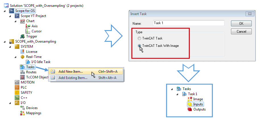
The Task has to be inserted as “TwinCAT Task With Image” and also creates an “Inputs” and “Outputs” folder therefore. The properties of the new (or as the case may be already existing) task must have activated the attribute “Create symbols” to make them selectable by the “Target Browser” of the Scope later on. The task cycle time has to be changed if so. Then, with10 x Oversampling 1 ms at 100 µs base time, resulting 10 ticks will be set by the usage of the EL3751 for example:
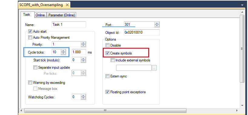
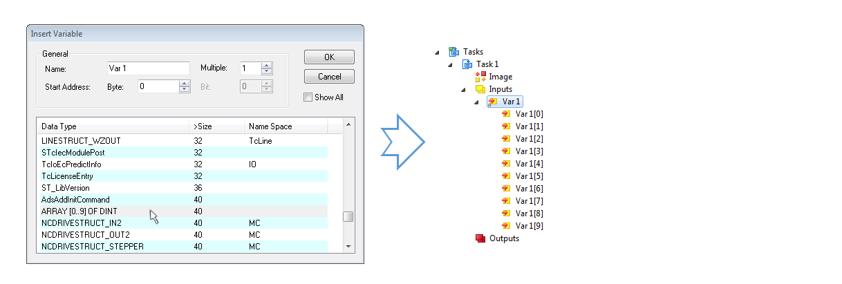
There’s a default value given for the Port number (301) that should be changed, if necessary. This number has to make acquainted for the Scope, if applicable, later on. By a right click on “Inputs” that oversampling based variable can now be appended with the fitting datatype of an array. „ARRAY [0..9] OF DINT“ referred to as „Var 1“ in this case:
Step 3: Linking an array variable with an oversampling PDO
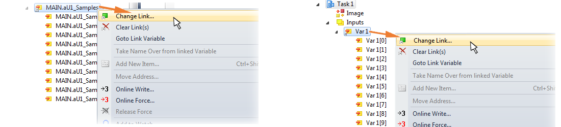
By right click on “MAIN.aUI_Samples” (according to the last preceding paragraph Step 2a) or rather “Var 1” of the free Task 1 (according to the last preceding paragraph Step 2b) within the Solution Explorer a window opens to select the process data:
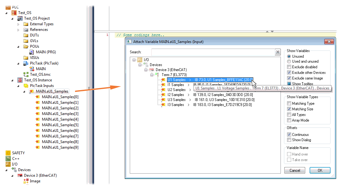
The selection of PDO "U1 Samples" of the EL3773 for “MAIN.aUI_Samples” based by the last preceding paragraph Step 2a as illustrated above have to be done in the same way for “Var 1” accordingly.
Step 4: Selection of the PLC array variable for the Y-axis of the scope
Now the configuration will be activated ( ) and logged in the PLC (
 ), so the array variable will be visible for the target browser of the scope for being selected.
Thereby the drop down menu will be opened by right clicking on “Axis” (A) for selection of the scope features (B):
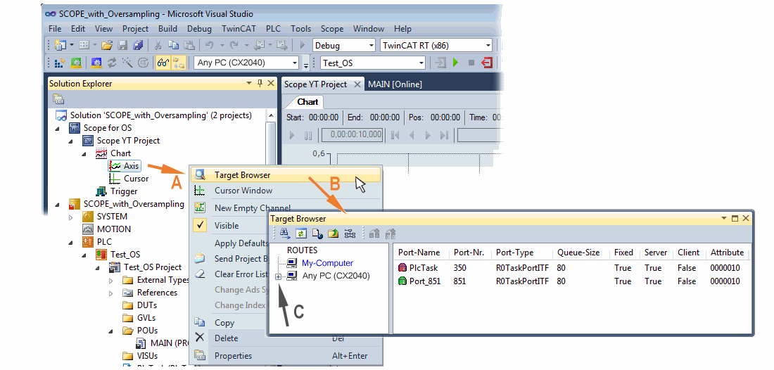
By addressing the corresponding system that represents the PLC containing the array variable (“Any PC (CX2040)” in this case) navigation up to the variable “aUI_Samples“ (C) have to be done.
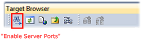
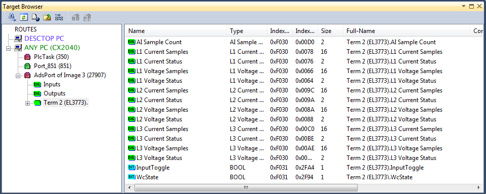
 | Variable don’t appears into the target browser If „ROUTES“ don’t offer a possibility for selection of the provided variables, the corresponding port should be declared for the target browser: |
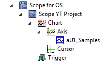
Using “Add symbol” displays the variable "aUI_Samples“ below “axis” within the scope project of the solution explorer directly.
Now the program start has to be done with  formally although there’s no program still yet. Using “Start Recording“
  the process data value of the oversampling PDO “L1 Voltage Samples “ via the linked PLC array variable can be recorded time dependent now.
As an example a sine wave input measurement value (204.5 Hz) will be illustrated below:
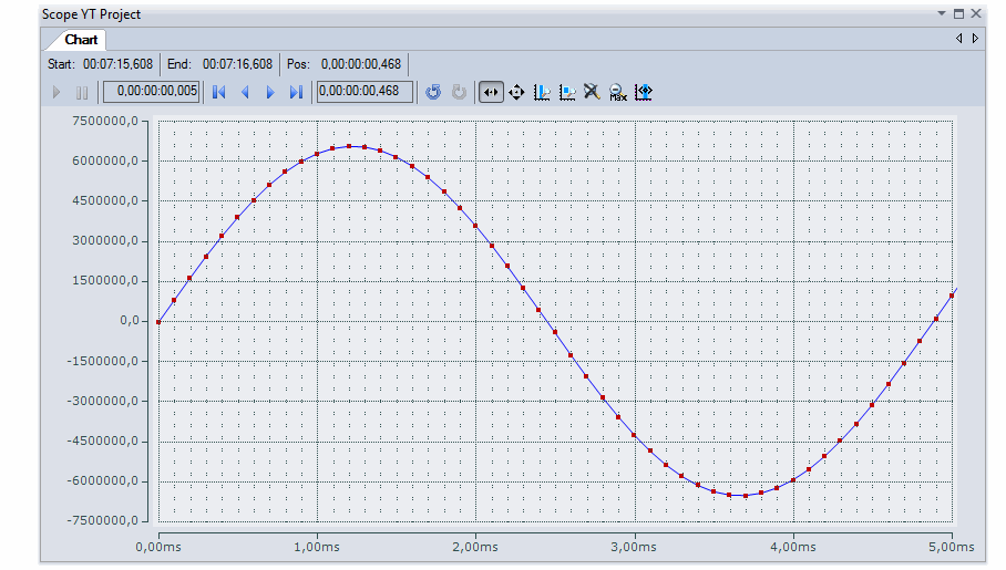
The X-axis view was fitted properly by using “Panning X”  after the recording was stopped
 . Following the “Chart” property “Use X-Axis SubGrid” was set to true with 10 divisions as well as the “ChannelNodeProperties” attribute “Marks” was set to “On” with the colors “Line Color” blue and “Mark Color” red. Therefore the latter indicates that 10 oversampling measurement points by the red marks.
Proceeding with / via ADS alternatively
In former TwinCAT 3 versions (or a lower revision as specified in the table above) the oversampling PDO of the respective oversampling able terminal/box can be made visible for the ScopeView by activation of the ADS server.
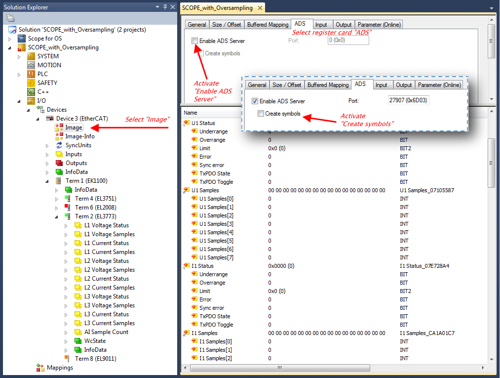
The activation of the server can be carried out by selection of “Image” within the left sided solution explorer:
„I/O → Devices → Device .. (EtherCAT) → Image“.
Next the register card “ADS” have to be selected to activate each checkbox „Enable ADS Server“ and „Create symbols“ then (the port entry is done automatically).
Thereby it is possible to access process data without an embedded POU and accordingly without a linked variable:
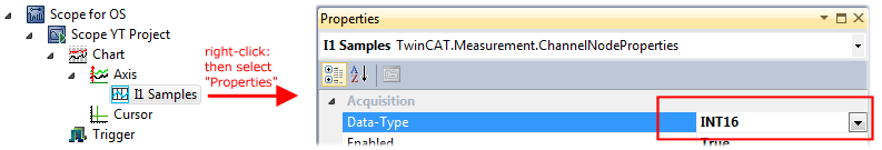
| Data type not valid It may happen that the target browser is unable to determine the data type after insertion of the oversampling PDO (according to an array variable usually). In this case it can be changed by the channel properties: |
| TwinCAT 3: Activate the ADS Server of an EtherCAT device Also see Beckhoff Information System: |