LIN Master Feature EL6001
Description of “LIN master support” (from FW10)
The EL6001 realizes a bus interface for RS232 levels. From software version 10, the EL6001 features an auxiliary function for sending and receiving LIN telegrams. This function does not cover the formal treatment of the protocol layers for LIN (“protocol stack”) or a physical LIN connection. Instead, the EL6001 can deal with the prolonged start/end mark of a LIN telegram in write and read direction.
”Above” the terminal a LIN stack is required that is implemented in the PLC, for example, “below” the terminal an RS232 <-> 5/12 V level converter e. g. “RS232-LIN” is required.
Before using this function, please check the suitability in your system, since the EL6001 does not have a fully comprehensive LIN implementation!
A complete LIN frame results from a master query with directly following slave response. The master sends the master frame and receives the slave data. With activated LIN functionality of the EL6001 a “sync break” and a “sync byte” is output before the “protected identifier” (PID).
In fact the EL6001 terminal is therefore able to operate under LIN as follows
- EL6001 operating as LIN master, sends data to the Slave and receives the response.
- EL6001 operating as LIN slave: the EL6001 terminal cannot respond to the master telegram in time! Therefore
- receive data from the master: yes
- send data to the master: no
Activation
The addition of a “sync break” and “sync field” for sending, which is required for LIN, can be activated via the “Command” object. To this end, enter the value 0x3000 in the CoE object 0xB000:01. The response can be read in CoE object 0xB000:03 with the values 0x01 0x00 0x00 0x4C 0x49 0x4E (4C 49 4E = ASCII “LIN”) as confirmation of the activation of this function. The terminal is then ready for receiving frames on the LIN bus containing the 13-bit “sync break” and the “sync field” (0x55), and to make only the following information in the receive data and to output these IDs during sending.
This setting is not permanently stored in the terminal and has to be written again after each new startup. The startup list can be used to circumvent this.
User-specific baud rate
Any already available baud rate and or the baud rate 10417 can be entered in the object “Explicit baudrate” (0x8000:1B).
Further parameters
The following settings within CoE object 0x8000 are necessary to ensure correct function in LIN mode:
Index:Subindex | Name | Value |
|---|---|---|
0x8000:01 | Enable RTS/CTS | FALSE |
0x8000:02 | Enable XON/XOFF supported tx data | FALSE |
0x8000:03 | Enable XON/XOFF supported rx data | FALSE |
0x8000:04 | Enable send FIFO data continuous | FALSE |
0x8000:05 | Enable transfer rate optimization | TRUE |
0x8000:15 | Dataframe | 3 (8N1) |
0x8000:1A | Rx buffer full notification |
Operation
The application of the control and status words remains unchanged in LIN mode.
In LIN mode, the EL6001 automatically precedes the user data with the “Break field” and the “Sync byte” field. During receiving these two fields are automatically removed.
The process image should be used as follows:
Process data | Contents |
|---|---|
Ctrl.Output length | Number of user data bytes (n) + 2 |
Data Out 0 | Protected ID field (PID = Protected identifier field) |
Data Out 1 | Data byte 1 |
|
|
Data Out n | Data byte n |
Data Out n+1 | Checksum |
EL6001 LIN example
The following LIN communication example is intended to illustrate that participation of a PLC controller via the EL6001 terminal in a LIN cluster is possible by activating the complementary LIN functionality via the 0xB000 CoE “command” object in combination with a physical conversion of RS-232 to the LIN bus.
Hardware connection based on a UART-LIN converter
The implementation of the physical layer as a basic prerequisite for LIN communication includes the provision of one-wire bus with corresponding signal levels 0V / 12V. This is best done with an RS232-LIN converter, which is connected to a sub-D connector and on the other side provides three poles for ground, power supply and the electrical connection to the one-wire LIN-bus.
The use of an RS232-LIN converter requires a sub-D 9-pin connector to be connected to the EL6001 terminal, as shown in the diagram:
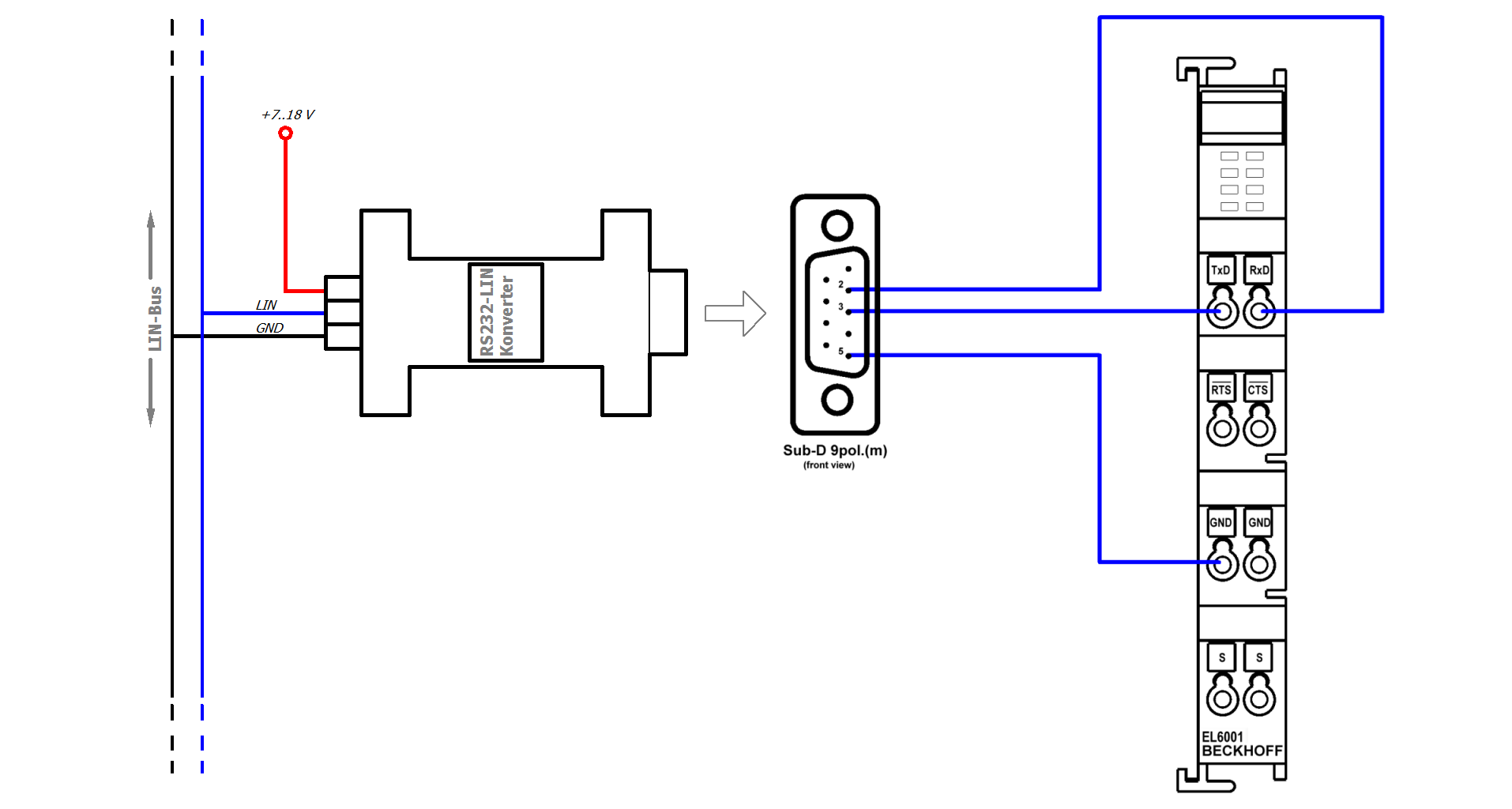 Fig.152: RS232-LIN sub-D connector connected to the EL6001 terminal
Electrical connections between the EL6001 terminal and the sub-D 9-pin connector:
- RxD →pin 2
- TxD →pin 3
- GND → pin 5
Programming in ST
A LIN communication can be represented by a PLC “master task”, whereby a master sends an “unconditional frame”, as usual with a LIN bus, and only outputs the PID (protocol identifier) of a known slave node on the LIN bus, thereby generally requesting data from the respective slave. The chapter on commissioning contains a relevant programming example.
In this example the slave has the ID 0x07; the master therefore sends the ID 0x07 on the bus, including the calculated parity, resulting in the PID field 0x47. The message on the LIN bus then looks as follows:
 Fig.153: LIN frame example: Query from master to node with ID 0x07
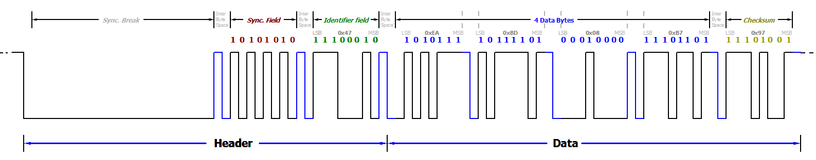 Fig.154: LIN frame example: ID0x07 with data 0xEA,0xBD,0x08,0xB7 + checksum 0x97
Oscilloscope recordings LIN frame with ID 0x07:
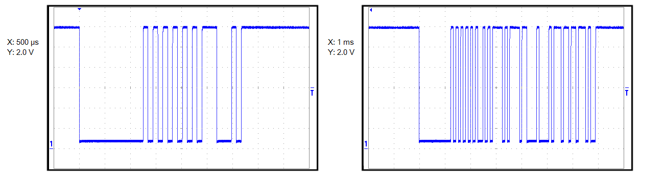 Fig.155: Left: Query on the LIN bus with PID 0x47, right: LIN frame with the same PID and data, including checksum