Servo Control Technology
The XTS Soft Drive is equivalent to a Servo Drive/Amplifier but three out of the four core functions are done in the Control PC’s software. A typical Servo Drive Configuration has the following setup.
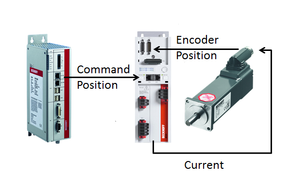
In Standard Servo Control systems, the Controller calculates the motion control profile and provides target positions to the Servo Drive at a fixed rate typically between 2ms and 250us. The Drive contains electronics that can do both the calculations (digital signal processing or DSP) and take the resulting number from those calculations and turn it into a current via pulse width modulation (PWM). The current goes to the motor, flows through coils and this provides a torque. The motor contains an encoder (or other position feedback) that the drive can read and has electronics to turn that back into a number. Thus Digital Servo Control with DSP’s and PWM. The drive performs 4 separate but related tasks.
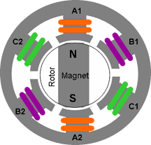
Current/Torque Control: The drive has to ensure the amount of current flowing through the coil matches with the amount of current requested. This is not a “set it and forget it” type of value at different speeds and temperatures the PWM must work differently to provide the same amount of current flow. Constant current flow = constant torque. Also as new current commands are issued the controller must react and provide the requested amount of current as quickly as possible. The control loop is not “continuous” it is done repeatedly at fixed intervals, usually 8000-32000 times per second. The actual current value is sampled, processed and a new command value is issued. The processing can be quite complicated and include things like filtering out specific frequencies. For the drive to have any chance controlling the motor this first loop must work well. If the current/torque/force cannot be controlled accurately nothing else will function. | Commutation: The motor has more than one magnet and more than one coil and so the drive must determine how much current each coil should receive and in which direction the current should flow through each coil. To generate a specific torque/force the drive uses the encoder position of the motor to determine how much current each coil should in order to provide the requested force/torque. This is the commutation process. This process is also fairly involved as the commutation process must keep the generated magnetic field ahead of the rotor so that the rotor keeps trying to catch it and creates a torque. With current control and commutation the torque of the motor can be controlled and therefore the acceleration can be controlled. If the goal was to simply control the acceleration of the motor the servo drive design would be complete. However the goal is to control the position of the motor. |
|
|
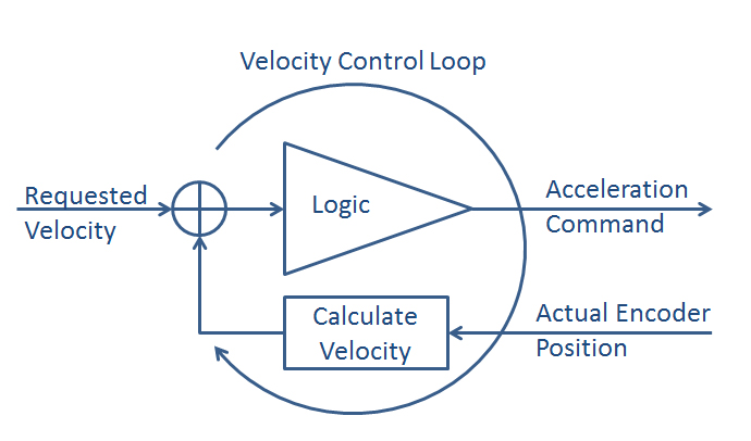
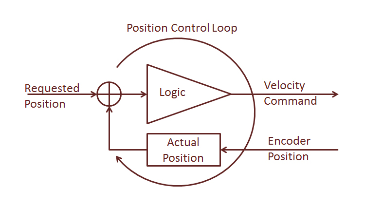
Velocity Control Loop:The third item the drive is responsible for is the velocity control loop, the first integral of acceleration and the first derivative of position. This control loop is generally not calculated as often as this loops needs sends commands to the control loop and operates on the results of the control loop. It takes time for the acceleration to result in a velocity (integration) and the position needs be measured more than once to calculate a velocity (derivative). This loop often runs at cycle times between 250us and 32.25us (4000Hz – 16000Hz). The velocity control loop takes a requested velocity and based on the actual encoder position an actual velocity is calculated and a new acceleration command is generated to speed the motor up or slow it down. For this loop to work properly the current control loop must work properly | The final control loop is the position control loop, this loop typically runs at the slowest update rate 500Hz to 4000Hz.This loop acts on the results of the velocity loop and issues new commands to the velocity loop. This loop takes uses the position as feedback and outputs a new commanded velocity. If the velocity loop doesn’t work the position loop has no chance to control the position. This loop works in exactly the same way as the velocity loop the position is the integral of velocity and velocity is the derivative of position. |
|
|
This is an extremely simplified view of what the drives control loops do. Often a drive will be provided with much more information to allow the drive to provide much better control. The Profile Generation (done by the motion controller) will often provide a Velocity and Torque/Force (Feed Forward) values in addition to Position. If it is known the motor must accelerate, a “starting point” acceleration/current will be given to the current control loop. In this way the current loop starts with this amount of current rather than waiting for the current loop to detect that the actual current is less than the requested current and then begin to increase the amount of current that is output. So why include an oversimplified version description of the drive functionality. The reason being that 3 of the 4 tasks a drive would do are now replaced with software. The only function that remains in the XTS Hardware Modules is the Current Control loop. The XTS Module receives a Current Command value for each coil and ensures each coil receives the requested current. All other control is done in the PC in software Based on the position of the mover the XTS Driver and soft drive determine which coils to activate with how much current so that the mover is provided with the requested force/acceleration. | |