Tuning in the Curve
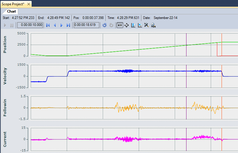
With the straight section tuned, the curves can be given separate tuning parameters if necessary. Here an entire loop of the track is run; it is very evident which sections of track correspond to the curves.
Step 1 | Step 2 |
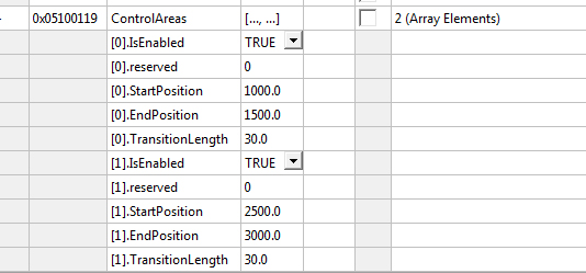
This system is a vertical system as such the load must be lifted and lowered through the curve. Also the center of gravity on this system is about 2cm from the magnets. This has a very large effect for how the system travels through the curve. | To enable the Tuning parameters for the curve first the Control Areas must be defined. This system has 2 curves one starting at 1000mm to 1500mm and one from 2500mm to 3000mm |
|
|
|
|
Step 3 | Step 4 |
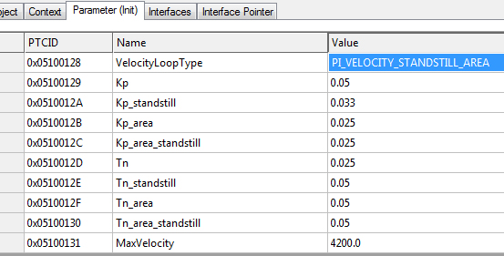
Then the Position Control Loop needs to be set to P_POSITION_STANDSTILL_AREA The values in Kp_area, Kp_area_standstill and PosLoopFilter_area are now active when the axis is in a defined and enabled Control Area | This allows the Kp_area and PosLoopFilter_area parameters to be used. The velocity Loop must be set to PI_VELOCITY_STANDSTILL_AREA With the Area parameters enabled, Kp_area and Tn_area, Kp_area_standstill and Tn_area_standstill are now active when the axis is within a defined and enabled Control Area. |
|
|
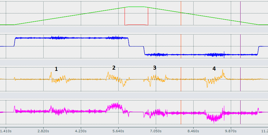
| Depending on the location of the center of gravity on the mover and the orientation of the XTS It is much more difficult to tune the system in the curves and it simply will not behave as well as when in the straight sections. |
Section 1 is entering the curve and lowering the mover. Section 2 entering the curve and lifting the mover. The motion is then reversed and 3 is running through the same curve as section 2 only backwards and lowering the mover, and section 4 is running through the curve lifting the mover. As the mover is lifted more current is applied as the mover rounds the corner less current is required and the mover overtakes its target positions. | |
The same sequence for tuning the straight section can be used to tune the curves. Once the area is defined:
Disable the Position Control Loop:
- Position Control Kp_area
- Position Control Kp_area_standstill
Tune the velocity control loop (in this case Velo Step Sequence may not be possible):
- Velocity Control Kp_area
- Velocity Control Tn_area
- Velocity Control Kp_area_standstill
- Velocity Control Tn_area_standstill
Enable and tune the Position Control Loop:
- Position Control Loop Kp Area
The mechanics of what is mounted to the mover will dictate how well it can be tuned. The ideal location for the center of gravity is centered directly between the magnets of the mover as this is where the force is applied. Adding a counter weight will increase the mass but can also drastically reduce the oscillations of the mover, particularly in the curve. Also adding a rubber buffer or a tuned mass damping system can drastically reduce mechanical oscillations. It can be that stiffer is not better. When a system is properly tuned it should follow the move very closely, different systems and different loads will have different results. However when properly fitted with tooling and load the mover should be able to follow the command with a lag distance of <1mm during acceleration and <+/-0.25mm at speed. Stopping should settle within +/-0.01mm within less than 100ms.
If no settings can be found that prevent oscillations, or give the desired settling time and response, the construction of the load must be re-designed OR a new mover type could be used. (50mm 12 roller mover or 70mm mid-range mover) Refer to the project planning guide for load design.