Dead time compensation
A prerequisite for high-precision conversion of positions into times and vice versa is precise dead time compensation of the axes. From TwinCAT 2.11 such a dead time compensation function is available for EtherCAT and Sercos axes. It operates largely automatically. Nevertheless, a manual configuration can be necessary, for example to compensate the drive's internal dead times.
Support of distributed clocks
Support for distributed clocks must initially be activated in EtherCAT drives as follows:
- 1. Call the drive's Ether CAT "Advanced Settings" dialog.
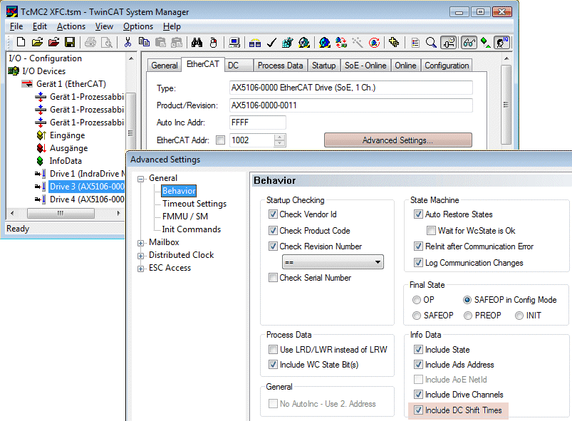
- 2. Activate the switch "Include DC Shift Times"
- The time information is made available in the info data ("InfoData") of the drive and later linked with the NC axis.
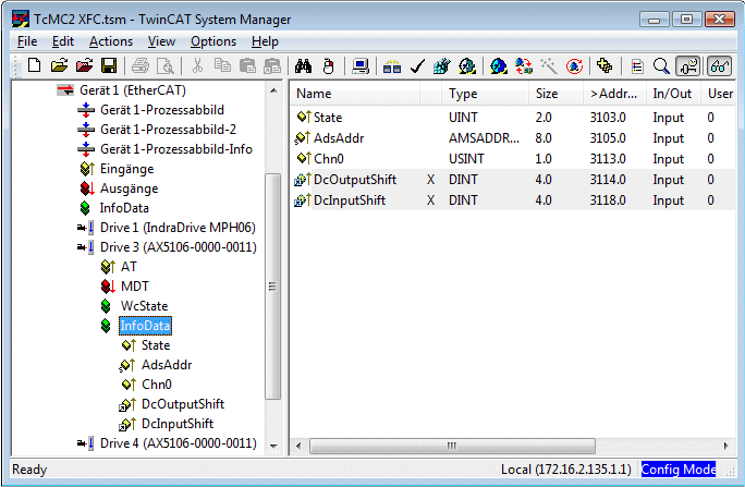
"DcInputShift" is the time required to transmit status information, such as the actual position of a drive, to the controller. In other words, it is the time between the acquisition and the evaluation of these data.
"DcOutputShift" is the time for the output of the process data to the drive, i.e. for the time delay between the calculation and the effect of these data.
The time information is provided dynamically by the system and is used by the NC for dead time compensation of an axis.
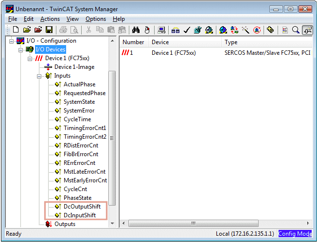
For Sercos axes the times DcInputShift and DcOutputShift are provided by the Sercos card and do not have to be configured. If a drive is linked to an NC axis these times are also linked.
Compensation of the encoder dead time
The dead time compensation for the data acquisition side is activated on the "Time Compensation" tab of the axis encoder. The dead time from DcInputShift provided by the system is used for calculating the compensation.
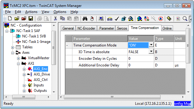
In special cases, for example in the event of additional dead times due to the hardware used, it may be necessary to configure further times.
The value Encoder Delay in Cycles indicates additional delays (whole I/O cycles). This time is therefore not a fixed value, but changes with the cycle time.
The value "Additional Drive Delay" is a fixed time value in µs caused by the hardware used.
Compensation of the drive dead time
The dead time compensation in the output direction is activated on the "Time Compensation" tab of the NC axis drive. As a result the time from DcOutputShift provided by the system is used for calculating the compensation.
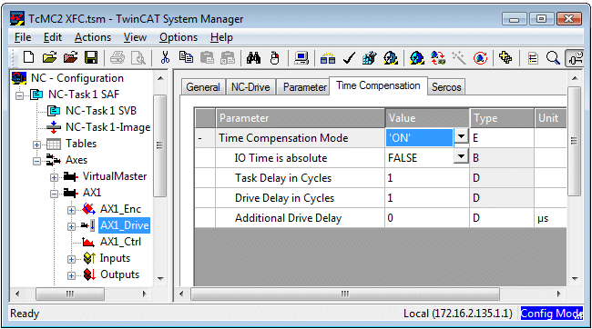
In special cases further times can be configured.
The value Task Delay in Cycles is based on the setting in the task configuration. Depending on the set task timing the dead time may be extended by one cycle.
The value "Drive Delay in Cycles" indicates additional delays by whole I/O cycles caused by the drive.
The value "Additional Drive Delay" is a fixed time value in µs caused by the hardware used.
Effect of dead time compensation
Dead time compensation is used for conversion of all NC data that are cyclically exchanged with the PLC (NcToPlc) to the current time. The actual position, set position and following error of the axis in particular refer to the current time and reflect the physical axis position at this time. The PLC can use these values for further high-precision time and position calculations. (See basic functions XFC_GetCurDcTaskTime , XFC_TimeOfPosition and XFC_PositionAtTime.)