ZoneImageLayout
The ZoneImageLayout framework control allows users to present temperature zones over an image background in a layout that mimics the physical arrangement on the machine. All the changes can be done directly from the client thus eliminating the necessity of accessing the project through engineering.
Based on the standard TcHMI Control, the ZoneImageLayout control uses the standard background image attributes such as BackgroundImage to display an image in the backdrop. Different attributes and dialogs allow user to change the background image and related properties directly from the client.
On top of the background the control portrays small tiles, with each tile presenting the actual status of a temperature zone.
User can use various attributes, dialogs, and touch/click interactions to move and arrange temperature zone tiles in different layouts.
 | ActivateConfig action Any new changes to the control must be activated using the ActivateConfig action to set new values to the PLC. |
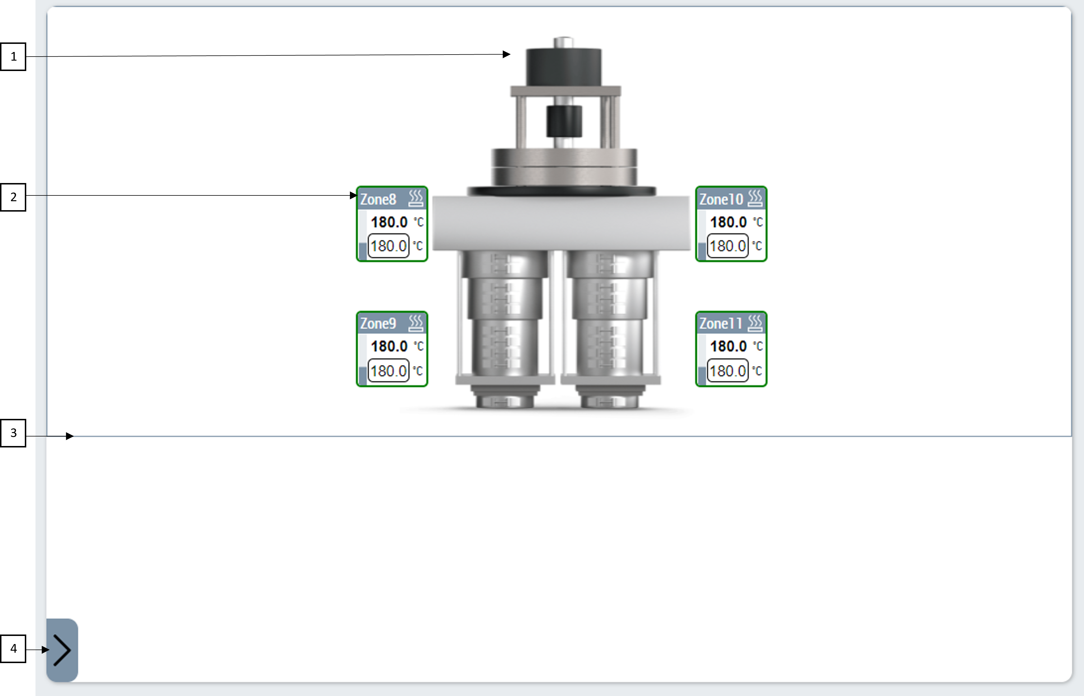
- Background Image displayed on the control.
- Temperature zones
- Layout area to guide user.
- Button to open zone selection dialog.
Tiles displaying zones
Each zone on the layout is represented with a visual element that gives more information of the linked temperature zone in the controller.
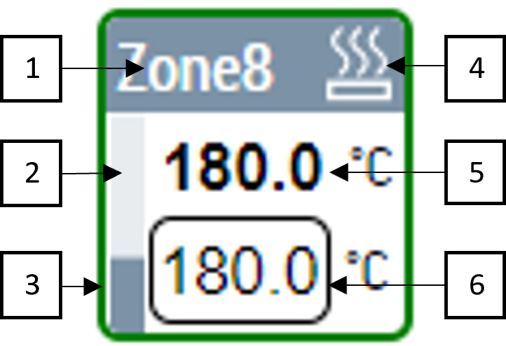
- ZoneName
- PowerLevel
- Border color indicating zone status
- Zone heating/cooling/error status
- ActualTemperature of the zone
- Input for user to write SetpointTemperature of the zone
Table below explains every possible border color and what it represents.
|
Border Color |
Zone Status |
|---|---|
|
Blue |
Zone actual temperature is very low. |
|
Green |
Zones actual temperature value is within inner tolerances band. |
|
Orange |
Zones actual temperature value is out of inner tolerances but within outer tolerance bands. |
|
Red |
Zones actual temperature value is out of outer tolerances band. |