Heating current monitoring
In the Plastics Processing Framework, heating tape monitoring is called "Looptest". This allows to detect the following malfunctions of a heating zone:
- Condition of the actuators
- Shorted Solid State Relays (SSR)
- "Sticking" contactors
- Condition of the heating tapes
- Partial and total failure
- Performance losses due to aging
Plastics machines are sometimes designed to contain several temperature control groups (extruders1..n, heating channels, etc.). These are partly supplied separately. These supply units are called supply groups in the framework. Each supply group consists of four supply lines and one power measurement terminal. Several heating zones can be connected to one supply line. Each heating zone contains an actuator (solid state relay - SSR or contactor), one or more heating tapes and a temperature sensor. The first supply line of a group represents the supply for the heating zones, which are connected between L1 and the neutral conductor. The second for L2 and N and the third for L3 and N. The fourth supply line includes all heating zones that are connected between two outer conductors in star or delta.

In the parameters of a heating zone, it is now possible to set in which supply line the zone is located and thus to which supply group it belongs. Furthermore, the nominal output of the heating element can be set in the parameters. This information is necessary so that the Looptest can assign the zone, test it and interpret its measurement.
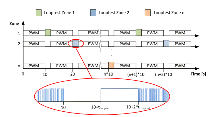
In the Plastic Processing Framework, there is one loop test per supply group. This passes through all heating zones. If it finds a zone that belongs to its supply group, it starts a measurement. For this purpose, all elements belonging to this group are switched off and the power is determined. This should be zero. If this is not the case, an actuator is defective. After a time tLooptest (default setting 200 ms) has elapsed, the heating element is switched on for the same time and the power is determined. This is compared with the nominal output of the heating zone. If it deviates by a set percentage value, an error is displayed. After that, the control is active for 10 seconds. The self-generated additional heating power is taken into account in the controller. After that, the next zone of the same supply group is searched.
The following figure illustrates this with an example. It is assumed that a plant has only one supply group, for example an extruder with n zones. The loop test is active and finds zone 1. As described before, all zones are switched off first and the power is measured. Zone 1 is then switched on for tLooptest and the power is measured again. In a cycle of 10 seconds, the next zone is tested using the same procedure.
The EL3403 calculates the power over an interval of 10 periods by default. The calculated power is then filtered using low-pass and high-pass filters. In addition, solid state relays, especially those that switch in zero crossing, have a not inconsiderable switching time. This leads to the fact that in some cases a usable power is measured only after 500 ms. With an interval of one period, the time could be reduced to 200 ms. Nevertheless, measuring errors of around 10% can occur under certain circumstances. If a correspondingly longer measuring time (e.g. 400 ms) is kept available, the accuracy increases considerably. An advantage of the xL3403 terminals is that the calculation of the power takes place within the terminal and thus no PLC computing time is required.
Implementation:
The following points must be observed for the implementation:
- FB_PowerMeasurement_TcPfw: This function block must be instantiated according to the number of terminals.
- ST_TcPfw_PowerMeasurement_Cfg: Must be created as ARRAY according to the terminal number.
- ST_TcPfw_PowerMeasurment_Ctrl: Must be applied as ARRAY according to the terminal number.
- ST_TcPfw_xL3403_State: Must be applied as ARRAY according to the terminal number. Even if no xL3403 is in use.
The mapping structures provided by the library for mapping to the power measurement terminal must be used and passed to the FB_PowerMeasurement_TcPfw function block as an address.
Notice | |
The pointer address and the stored terminal type must match at all times. Otherwise there will be wrong memory accesses. |