Service Mode
Three sources for switching requests and value specifications are available for the services:
- Manual operation (e.g. via OPC UA):
Operator - Internal PLC logic:
Automatic-Internal - Control system (e.g. via OPC UA):
Automatic-External
Operation mode control
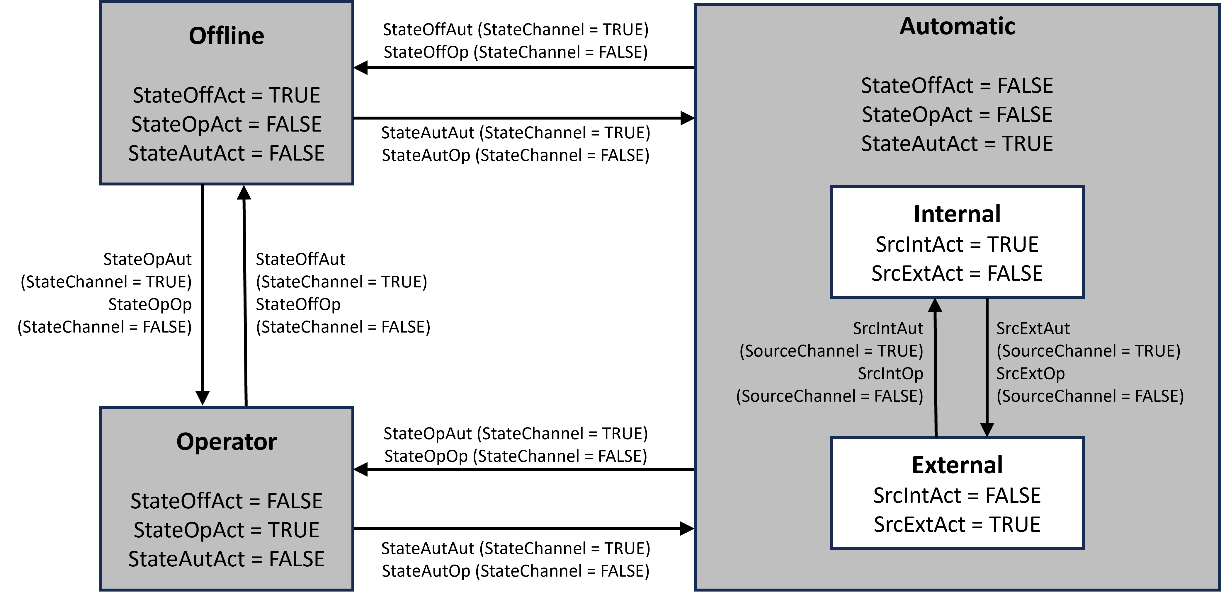
The operation mode control allows you to switch between the states Offline, Operator, and Automatic.
In the Offline state, no new switching requests or value specifications are taken into account. In the Operator state, *OP switching requests and *OP setpoints are processed; in the Automatic state, *Aut switching requests and *Aut value specifications from the selected source are processed.
The current state is displayed via the outputs StateOffAct, StateOpAct, and StateAutAct.
The state change is carried out via the internal PLC logic or via the operators. The input StateChannel is set via the internal PLC logic and specifies which source is taken into account during processing.
If more than one state change is requested at the same time (e.g., StateOpAut = TRUE and StateOffAut = TRUE), the requests are discarded and Operation Mode remains in its current state.
Source selection (Automatic)
The source selection is used in the Automatic operation mode and allows you to switch between Automatic-Internal and Automatic-External.
Automatic-Internal switching requests and value specifications are written by the internal PLC logic. The variable names are extended by the suffix *Int.
Automatic-External Switching requests and value specifications are written manually (e.g. via OPC UA).
Operator switching requests are made manually (e.g. via OPC UA). They are declared as external variables and cannot be written via the internal PLC logic. Operator switching requests, add the suffix *Op to the variable name.
If both state changes are requested simultaneously (e.g., SourceManAut = TRUE and SourceIntAut = TRUE), the requests are discarded and Source Mode remains in its current state.
 |
|
Diagram of the state machines:
The state machines work according to the following diagram:
 Inputs
Name | Type | Description | OPC UA access |
|---|---|---|---|
StateChannel | BOOL | Selection of switching requests for the operation mode of the state machine: 1: 0: | Read |
StateOffAut | BOOL |
| Read |
StateOpAut | BOOL |
| Read |
StateAutAut | BOOL |
| Read |
SrcChannel | BOOL | Selection of switching requests for the source of the state machine: 1: 0: | Read |
SrcIntAut | BOOL |
| Read |
SrcManAut | BOOL |
| Read |
 Outputs
Name | Type | Description | OPC UA access |
|---|---|---|---|
StateOffAct | BOOL | 1: Current operation mode is | Read |
StateOpAct | BOOL | 1: Current operation mode is | Read |
StateAutAct | BOOL | 1: Current operation mode is | Read |
SrcIntAct | BOOL | 1: The current source is | Read |
SrcManAct | BOOL | 1: The current source is | Read |
External variables
Name | Type | Description | OPC UA access |
|---|---|---|---|
StateOffOp | BOOL |
0→1: 1→0: Request has been processed. | Read/write |
StateOpOp | BOOL |
0→1: 1→0: Request has been processed. | Read/write |
StateAutOp | BOOL |
0→1: 1→0: Request has been processed. | Read/write |
SrcIntOp | BOOL |
0→1: 1→0: Request has been processed. | Read/write |
SrcManOp | BOOL |
0→1: 1→0: Request has been processed. | Read/write |
 Methods
Name | Type | Description |
|---|---|---|
IsOffline | BOOL | Returns |
IsOperator | BOOL | Returns |
IsAutomaticInternal | BOOL | Returns |
IsAutomaticExternal | BOOL | Returns |
SetOffline | BOOL | Sets the Returns |
SetOperator | BOOL | Sets the Returns |
SetAutomaticInternal | BOOL | Sets the Returns |
SetAutomaticExternal | BOOL | Sets the Returns |