"Logics" submenu
The submenu can be opened by clicking on the name in the table. The selected row is highlighted in blue in the table. All settings for the respective logic can be adjusted in the menu that opens. In the following section, a distinction is made between the different logic types for each page.
General (Logic):
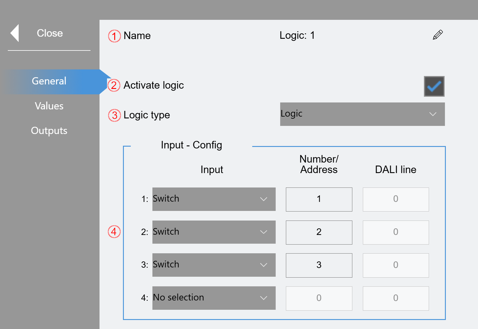
(1) The displayed name can be edited here.
(2) Activate logic. Only active logics are processed by the program.
(3) The logic type can be selected here. You can select either "Logic", "Threshold" or "Timer".
(4) Settings of the inputs:
Up to 4 inputs can be selected. Depending on the type, the Number/Address and DALI line must be specified.
General (Threshold/Timer):
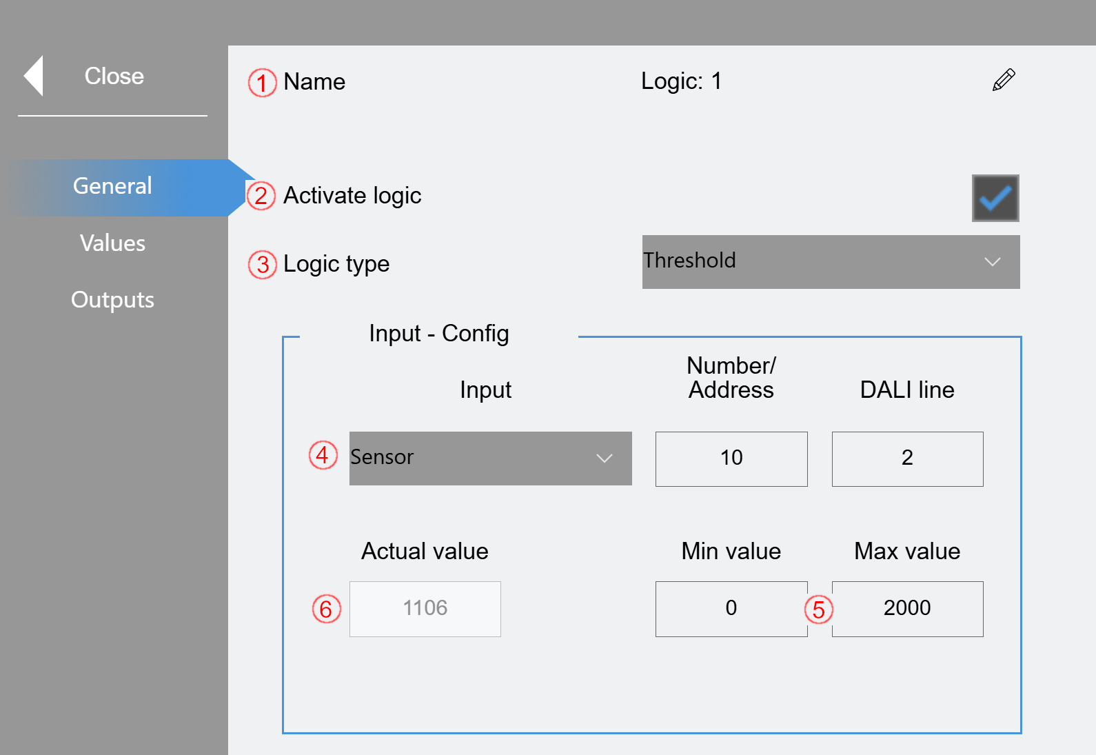
(1) The displayed name can be edited here.
(2) Activate logic. Only active logics are processed by the program.
(3) The logic type can be selected here. You can select either "Logic", "Threshold" or "Timer".
(4) Settings of the input:
Either "External Value" (GVL_LS_IO.bIn_Sensor_Brightness[x,y]), "Group" or "Sensor" can be selected. Depending on the selection, the other parameters must be specified accordingly.
(5) "Threshold" only: Specification of a min. and max. value to scale the input value accordingly.
(6) "Threshold" only: Display of the actual value
Values (logic):
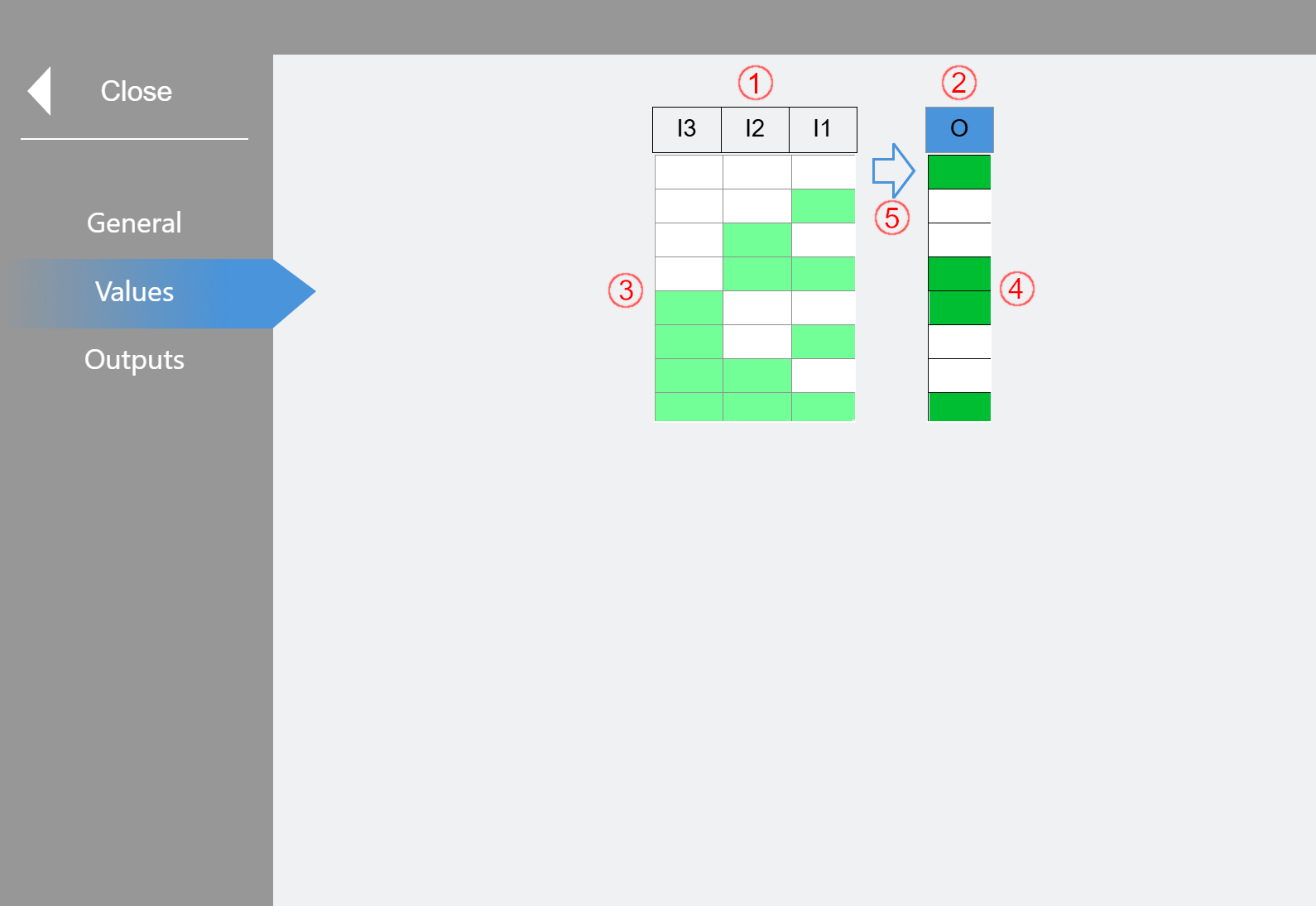
A classic logic table is displayed (here for 3 activated inputs: I1-I3).
(1) Inputs column (Input: "I1" - "I4")
The upper elements provide blue feedback when the respective input is switched "On".
(2) Output column (Output: "O")
The upper element gives blue feedback when the output is switched "On" according to the logic.
(3) All possible combinations of I1-I4 (if activated) are listed in the table. White means "Off", green means "On".
(4) In the Output column, the target status of the output can be set in accordance with the input image (3) of the same row by clicking in the respective cell. White means "Off", green means "On".
(5) The arrow jumps to the line that shows the actual status for orientation.
Values (Threshold):
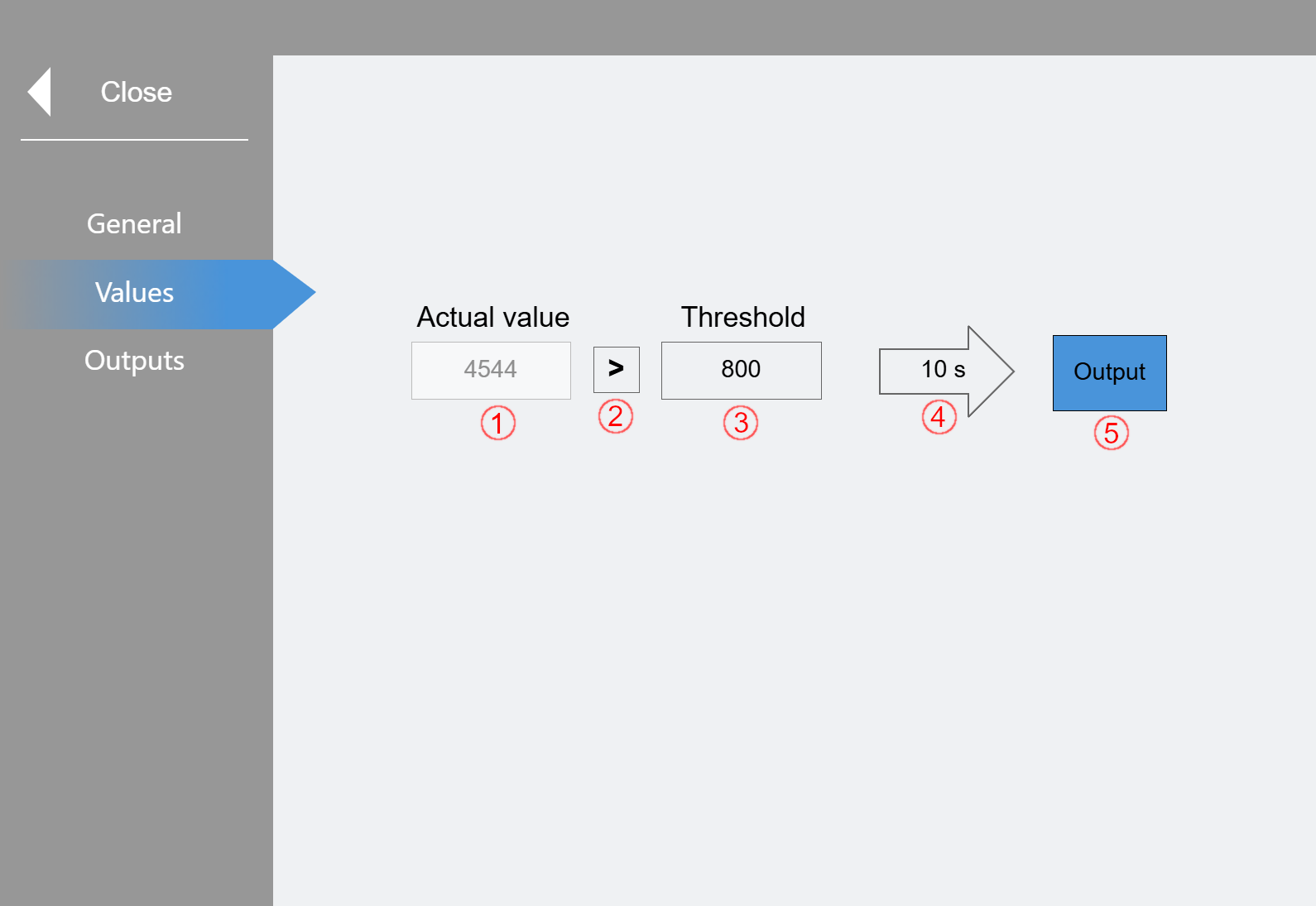
(1) Actual value display
(2) Setting the threshold logic can be switched between ">" and "<" by clicking.
(3) Specification of the threshold value
(4) Time delay until the output is set.
(5) Output display is highlighted in blue when it is active
In the example shown, the actual value must be greater than the threshold for 10 seconds for the output to switch.
Values (Timer):
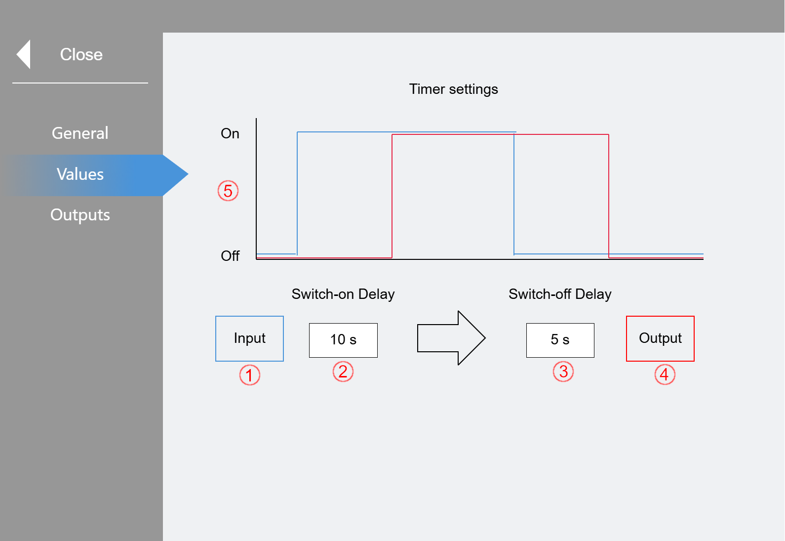
(1) Feedback of the input
(2) A switch-on delay can be specified (0-3600 s). The input must be set for this duration so that the signal is switched through.
(3) A switch-off delay can be specified (0-3600 s). The output is only switched off after the set time has elapsed.
(4) Feedback of the output
(5) Schematic representation of the set timer.
Outputs:
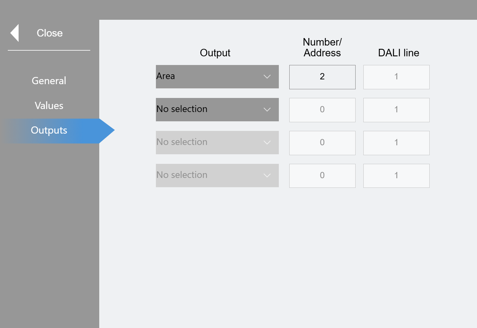
Up to 4 outputs can be set up in parallel here. In each case, it is possible to either enable an area, switch a group directly or describe an external input. If group is selected, the specified group "x" is overridden by 100%.