Representation of the DBC contents
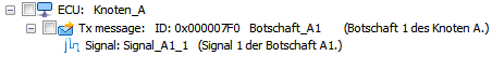
On the Import tab, the nodes of the DBC file are displayed in the following hierarchy:
|
|
|
Signal
Level | Symbol | Meaning | Structure of the text |
|---|---|---|---|
Node (ECU)
|
| Network device | ECU: %Name of the node% |
Message
|
| CAN message transmitted by the associated node | Tx message: ID: %id% [(29-bit ID | Multiplexed)] %Name of the message% [%(Comment)%] |
Signal
|
| Signal within the assigned CAN message | Signal: %Name of the signal% [%(Comment)%] |
|
|
|
|
Further symbols: | |||
|
|
|
|
Rx message
|
| CAN message received from the associated node | Rx message: ID: %id% [(29-bit ID | Multiplexed)] %Name of the message% [%(Comment)%] |
Signal (Multiplexer) |
| Multiplexer switch signal | Multiplexer signal: %Name of the signal% [%(Comment)%] |
Signal (multiplexed)
|
| Multiplexed signal | Multiplexed signal: (at value %Multiplexor%) %Name of the signal% [%(Comment)%] |
Node (simulated)
|
| Network device that can be simulated. | ECU: %Name of the node% |


*data placed in [ ] are only displayed if they apply or exist in the DBC file.