Configuration of the data objects
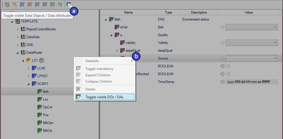
In the working area for the data model, you can show all of the objects additionally defined for the node in the standard via the toolbar (a) or via the context menu (b) using the command Toggle visible DOs / DAs.
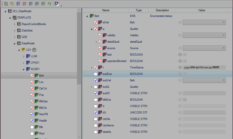
In addition, all objects are given a checkbox with which the optional objects can be added or deselected. The checkbox tick is blue for optional objects and red for required objects. Required objects can also be switched on and off via a command in the context menu of the respective object. However, in the interests of the standard this is not advisable.
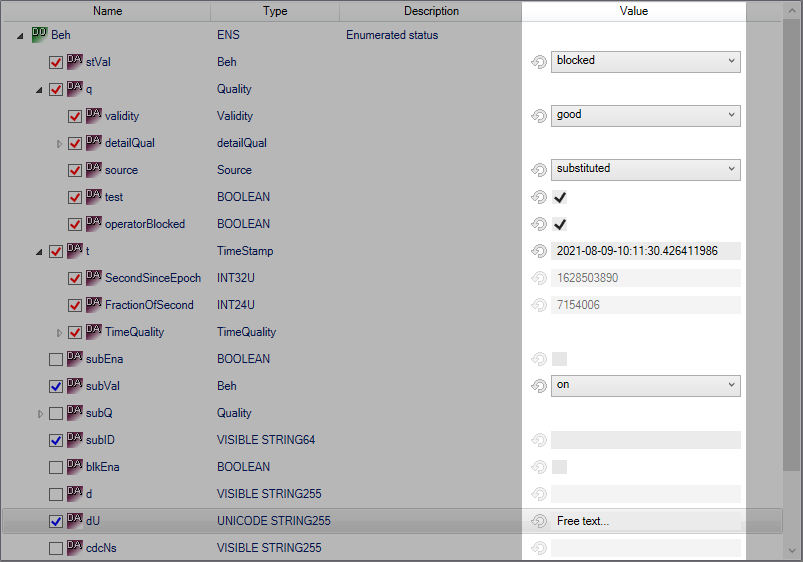
Default values can be set for the selected attributes in the Value column. To avoid unintentional entries, this is not possible for deselected attributes. Many objects offer enums, which enable a selection via a drop-down box. Numbers and texts can be entered directly. These values are later exported to the PLC code. The adjacent reset button allows you to delete the configured value.
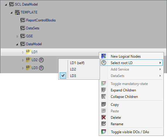
Logical Devices Management Hierarchy
To model complex functions, it may be necessary to group several logical devices into a management hierarchy. This is built up with the attribute setSrcRef of the object GrRef in the Logical Node LLN0 by optionally referencing a Logical Device via the value of the attribute. If no other logical device is referenced in a logical device, it is itself considered a root logical device. Representative for this, in the TwinCAT Telecontrol Configurator the name of the own Logical Device is provided with a (self) label to make this clear. The root logical device can be additionally specified in the context menu of the logical device.
Condition-dependent data objects
In addition to the required and optional objects, there are also the condition-dependent data objects, which may be present, be added or not be present in the data model, depending on the condition. Condition-dependent data objects are handled differently in the Configurator, depending on the condition. If a condition is not automatically handled by the Configurator, a message is displayed at the respective object. In addition, a ToolTip is displayed which contains the respective condition description.
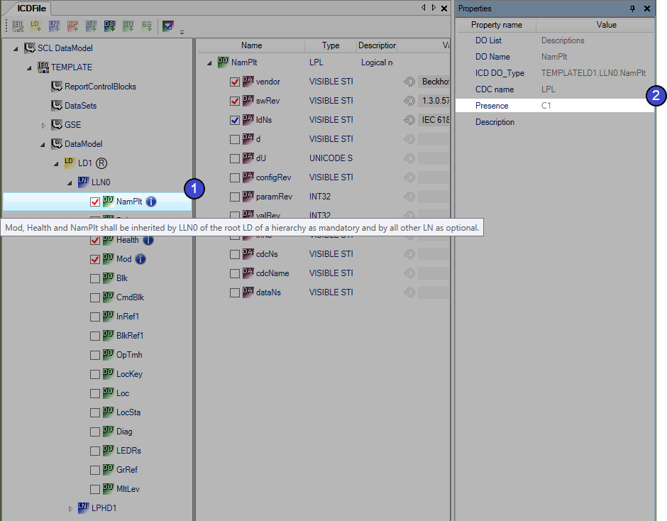
The following example shows how the condition C1 of the Common LN Logical Node was integrated. This Logical Node represents the basis of all Logical Nodes and is inherited from them. In the Logical Node LLN0, the three objects NamPlt, Health and Mod are added as required according to the standard. In the ANCR1 Logical Node, however, they are listed only as optional, since the LLN0 Logical Node of the Root Logical Device is not involved.
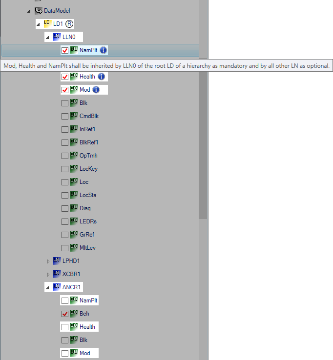
In the Properties window of the respective data object, you can see the condition designation under which you can find the condition in the IEC61850 standard.