FB_GseSvPhsMeasGeneratorClass
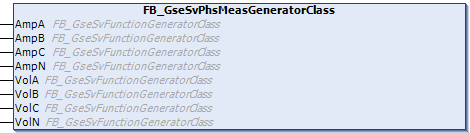
This function block implements 8 test signal function generators according to the “PhsMeas1” data set of the UCA 61850-9-2LE (Light Edition). This function block can be used to generate simulation values for phases A, B, C, and N (up to 4 currents and 4 voltage values) for an SV communication test.
Namespace: Tc3_Gse
Library: Tc3_Gse (Tc3_Gse.compiled-library)
FUNCTION_BLOCK FB_GseSvPhsMeasGeneratorClass
VAR_INPUT
AmpA: FB_GseSvFunctionGeneratorClass; (* "InnATCTR1.AmpSv.instMag.i" signal function generator *)
AmpB: FB_GseSvFunctionGeneratorClass; (* "InnBTCTR2.AmpSv.instMag.i" signal function generator *)
AmpC: FB_GseSvFunctionGeneratorClass; (* "InnCTCTR3.AmpSv.instMag.i" signal function generator *)
AmpN: FB_GseSvFunctionGeneratorClass; (* "InnNTCTR4.AmpSv.instMag.i" signal function generator *)
VolA: FB_GseSvFunctionGeneratorClass; (* "UnnATVTR1.VolSv.instMag.i" signal function generator *)
VolB: FB_GseSvFunctionGeneratorClass; (* "UnnBTVTR2.VolSv.instMag.i" signal function generator *)
VolC: FB_GseSvFunctionGeneratorClass; (* "UnnCTVTR3.VolSv.instMag.i" signal function generator *)
VolN: FB_GseSvFunctionGeneratorClass; (* "UnnNTVTR4.VolSv.instMag.i" signal function generator *)
END_VAR Inputs
Name | Type | Description |
|---|---|---|
AmpA | Test signal function generator for phase A current samples. | |
AmpB | Test signal function generator for phase B current samples. | |
AmpC | Test signal function generator for phase C current samples. | |
AmpN | Test signal function generator for current samples from phase N (neutral conductor). | |
VolA | Test signal function generator for the voltage samples of Phase A. | |
VolB | Test signal function generator for sampling the voltage of Phase B. | |
VolC | Test signal function generator for the voltage samples of Phase C. | |
VolN | Test signal function generator for sampling the voltage of phase N (neutral conductor). |
 Methods
Name | Description |
|---|---|
The method generates a new sample value for 4 currents and 4 voltages of the phases: A, B, C, and N. In the signal sampling mode 'AtPlcTaskCycleTime' (standard), this method is called nOversampleFactor times in each PLC task cycle. | |
The method configures all 8 test signal function generators based on the selected signal sampling mode (eMode), the PLC cycle time, the PLC cycle time correction factor (fCycleTimeCorrectionFactor), the configured oversampling factor (nOversampleFactor), the configured sampling rate (nSpecifiedSmpRate), and the signal frequency (fFrequency). The Config method is automatically called internally whenever these configuration parameters are changed. | |
For all 8 test signal function generators, this method resets the output values fSignal to 0 and the sample number nSample to 0. After the reset method is called, the next call method generates the first sample value with the number 0 again. If the configuration parameters are changed, the reset method is automatically called internally by the config method. |
 Properties
Name | Type | Access | Description |
|---|---|---|---|
bValid | BOOL | Get | Provides a cumulative configuration status for all 8 test signal function generators. TRUE => Configuration is correct; FALSE => Configuration is incorrect. An incorrect configuration is caused by invalid parameter values: fCycleTimeCorrectionFactor <= 0, fFrequency <= 0, nOversampleFactor = 0, or nSpecifiedSmpRate = 0. |
eMode | Set | Signal sampling mode. Default value: 'AtPlcTaskCycleTime' => Sampling within the PLC task cycle. The sampling rate is determined by the cycle time of the PLC task and the frequency. In sampling mode: "AtSmpRatePerPeriod" or "AtSmpRatePerSecond," the parameter value "nSpecifiedSmpRate" determines the sampling rate. | |
fCycleTimeCorrectionFactor | LREAL | Set | Sets the correction factor for the PLC task cycle time. Default value: 1.0 (no correction). Values <= 0 are invalid. |
fFrequency | LREAL | Set | Sets the signal frequency in Hz. Default value: 50 Hz. Values <= 0 are invalid. |
nOversampleFactor | UINT(1..128) | Set | Sets the oversampling factor of the signal generator. The value 0 is invalid. Default value: 1 (no oversampling). In the IEC 61850-9-2LE configuration, for example, the oversampling factor is set to 1 for the MSVCB01 signal generator and to 8 for the MSVCB02 signal generator. |
nSpecifiedSmpRate | UINT | Set | The sampling rate specified in sampling mode: ’AtSmpRatePerPeriod‘ or ’AtSmpRatePerSecond‘. The value 0 is invalid. Default value: 80. In sampling mode: 'AtPlcTaskCycleTime', this parameter value is ignored and not used. |